Control System, Rock Drill Rig And Control Method

Inactive Publication Date: 2012-04-12
EPIROC ROCK DRILLS AB +1
View PDF8 Cites 12 Cited by
  • Summary
  • Abstract
  • Description
  • Claims
  • Application Information

AI Technical Summary

Problems solved by technology

Such a control system can be a very complicated hydraulic system with highly customized valves, a complete electro-hydraulic sy

Method used


Image

  • Control System, Rock Drill Rig And Control Method
  • Control System, Rock Drill Rig And Control Method
  • Control System, Rock Drill Rig And Control Method

Examples


Embodiment Construction

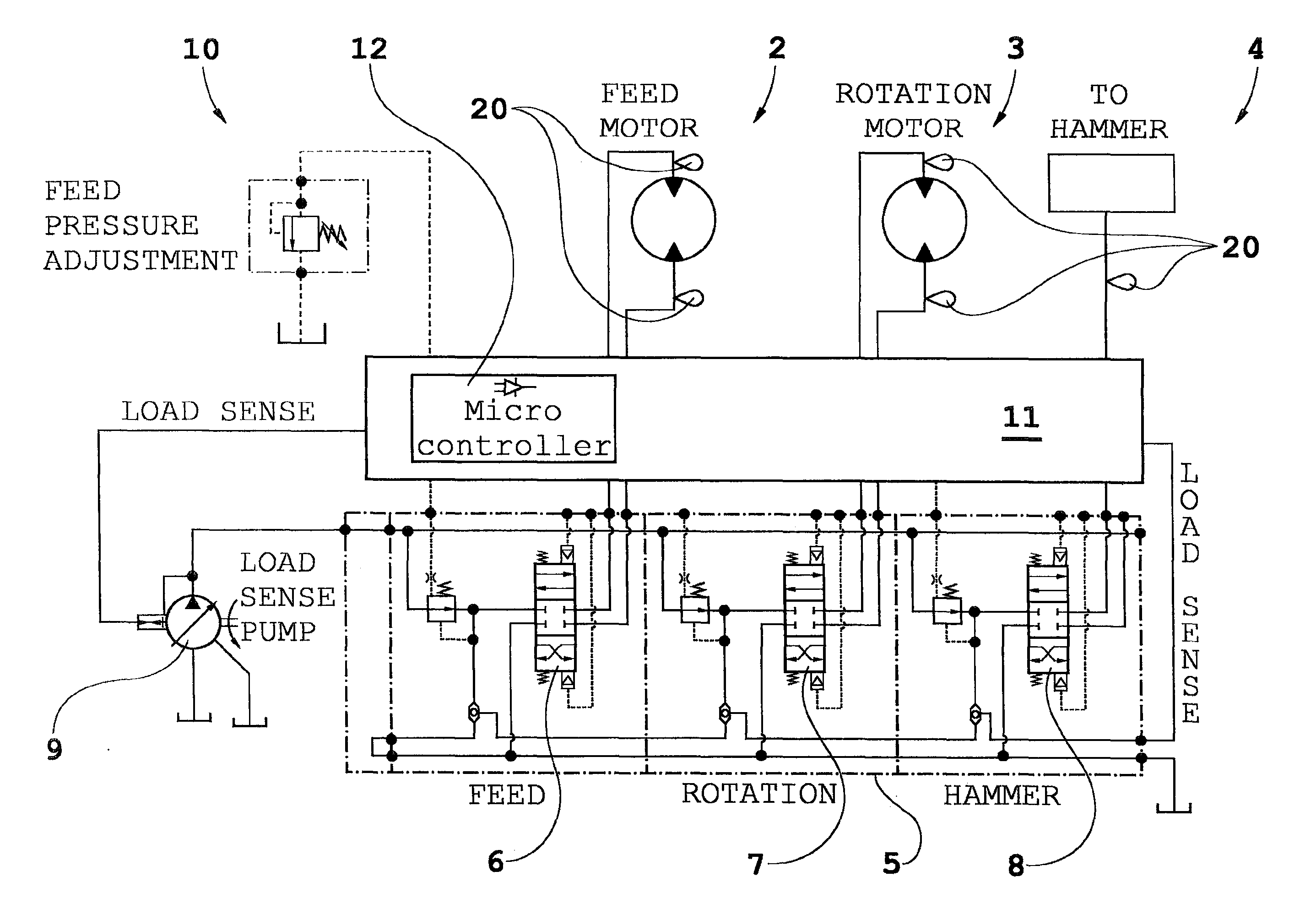
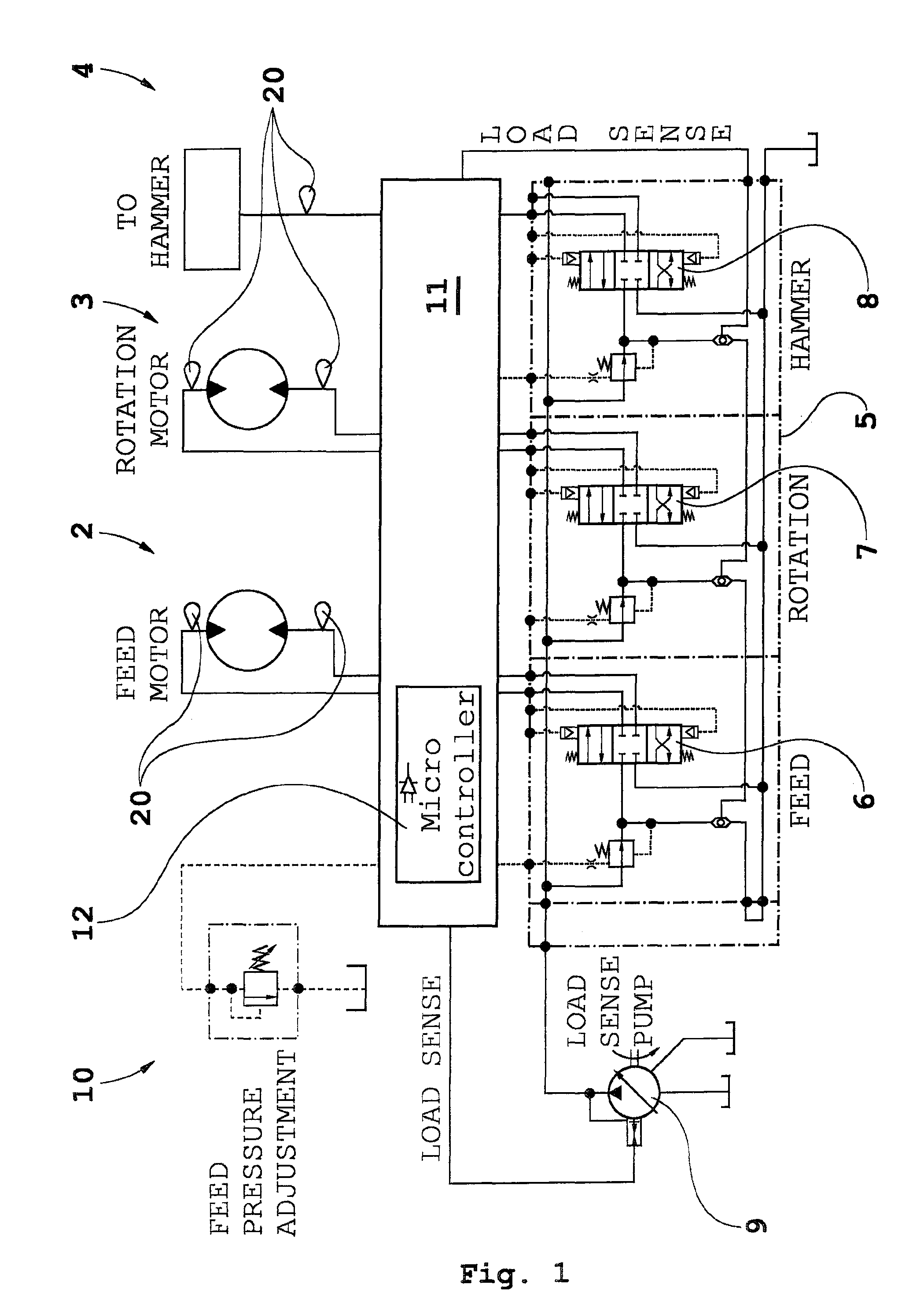
[0024]In FIG. 1 is indicated a control system 1 for a rock drill rig. A number of consumers: a feed motor 2, a rotation motor 3 and a percussive device or hammer 4 are connected over fluid conduits being hydraulic fluid to an operator controlled basic control system 5 (within dash dotted lines). This basic control system 5 includes regulating valves 6, 7 and 8, that are operator controlled. A pump of a load sensing type is indicated with 9 and a pressure limiting valve with 10.

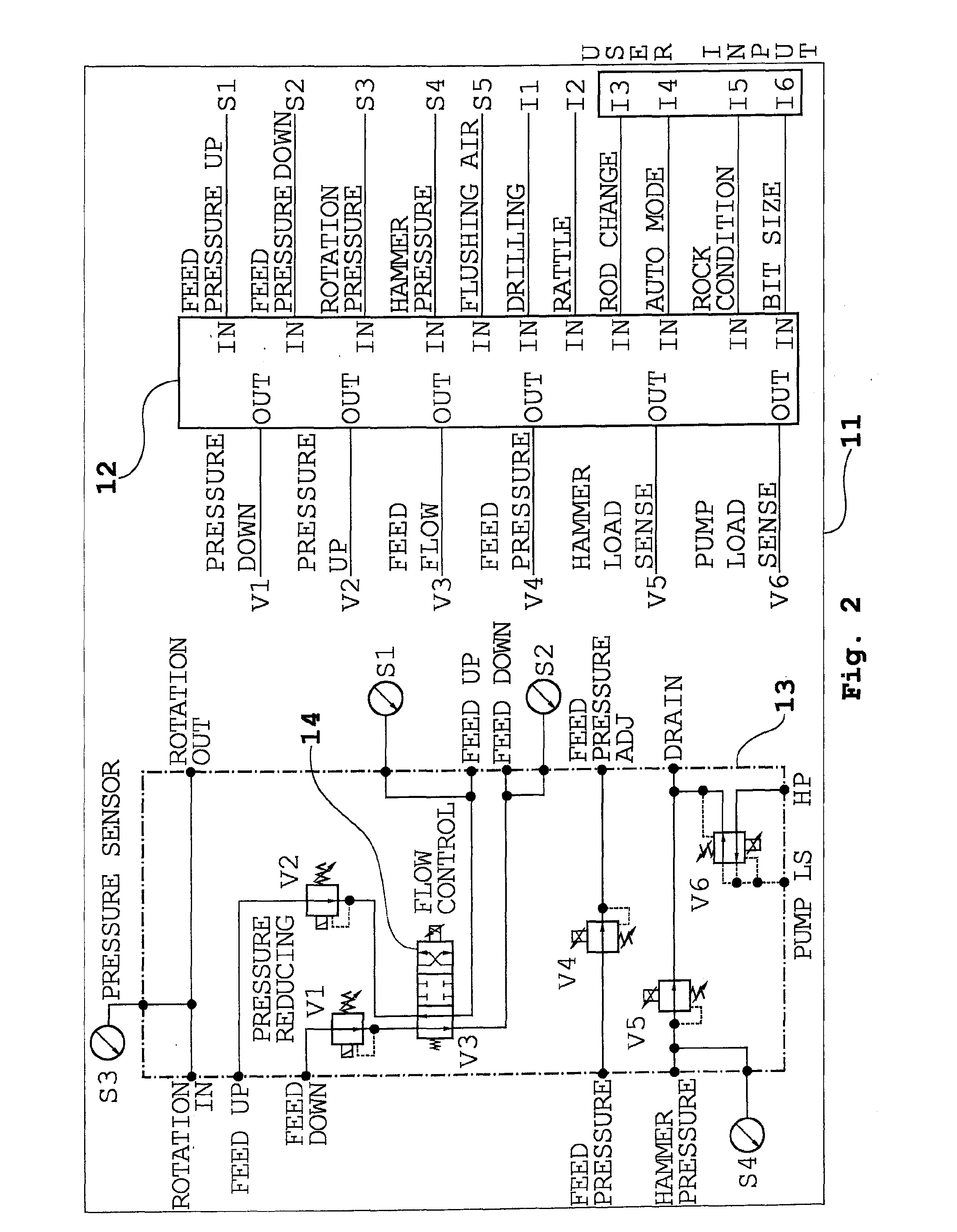
[0025]An electronically controlled auxiliary control unit 11 is interconnected in the fluid conduits so as to intercept in at least one of the fluid conduits. The auxiliary control unit includes at least one electrically controlled auxiliary valve for the connection to the respective fluid conduit and at least one sensor 20 for sensing prevailing fluid parameter values in at least one of the consumers 2-4. Sensor signals are sent over (not shown) signal cables to the auxiliary control unit as sensor input sign...


PUM


Abstract

A hydraulic fluid control system (1) for the control of pressure fluid supply to consumers being a feed motor (2), a percussion device (4) and a rotation motor (3) of a rock drilling machine, said system including a regulating valve (6,7,8) for each one of the consumers (2,3,4), wherein fluid conduits lead between the regulating valves and the respective consumers, the system having:
    • an electronically controlled auxiliary control unit (11) which includes at least one electrically controlled auxiliary valve (14) for the connection to and intercepting in at least one of the fluid conduits,
    • at least one sensor for sensing prevailing fluid parameter values in at least one member of the rock drilling machine the and sending sensor signals to the auxiliary control unit as sensor input signal is-values, and
    • a processor (12) having at least one parameter sensor input signal entry (S1-S5, I1-I5) for receiving said sensor input signal is-values and at least one control signal exit (V1-V6) for signal control of a respective auxiliary valve, wherein the processor (12) is arranged to compare said sensor input signal is-values with parameter should-values and to emit control signals to at least one of the auxiliary valves as a response to the result of the comparison in order to adjust fluid flow in the fluid conduit related to said at least one of the auxiliary valves. The invention also concerns a rock drill rig and a method.

Description

FIELD OF THE INVENTION[0001]The invention concerns a control system for the control of pressure fluid supply to consumers being a feed motor, a percussion device and a rotation motor of a rock drilling machine, said system including a regulating valve for each one of the consumers, wherein fluid conduits lead between the regulating valves and the respective consumers. The invention also concerns a rock drill rig including such a system and a control method.BACKGROUND OF THE INVENTION[0002]In a conventional rock drilling process, drilling parameters are set manually by a skilled operator through directly manipulating the different main hydraulic control valves. Although experienced operators can be said to have some feel for when a rock drilling process is running effectively, there is much to be wished when it comes to total control over the drilling process in order to drill more efficient while taking account on how the equipment should be operated most effectively and still avoid...

Claims


Application Information

Patent Timeline
IPC IPC(8): E21B4/06G05D7/00
CPCE21B44/06E21B7/025E21B47/08F15B21/087
Inventor JIAO, DEYICHENG, EUGENESINNERSTAD, JONASGUSTAVSSON, HANS
Owner EPIROC ROCK DRILLS AB
Why Eureka
Try Eureka