Wireless communication high-frequency circuit and wireless communication apparatus

a high-frequency circuit and wireless communication technology, applied in multiple-port networks, waveguide type devices, gated amplifiers, etc., can solve the problems of reducing transmission efficiency, difficult to compose matching circuits, and insufficient so as to improve transmission efficiency, reduce loss, and improve the effect of impedance matching between amplifiers and duplexers

Inactive Publication Date: 2012-04-12
MURATA MFG CO LTD
View PDF11 Cites 39 Cited by
  • Summary
  • Abstract
  • Description
  • Claims
  • Application Information

AI Technical Summary

Benefits of technology

[0054]According to various preferred embodiments of the present invention, the impedance matching between the amplifier and the duplexers is improved and the loss is reduced to improve the transmission efficiency.
[0055]In addition, the wireless communication high-frequency circuit is preferably designed so that the impedance when the second relay switch is viewed from the antenna is varied depending on which duplexer the path to which the contact of the second relay switch is connected leads to (that is, the antenna impedance is appropriately changed for every communication frequency band). Consequently, the radiation efficiency of the antenna in each communication band is improved.

Problems solved by technology

However, when the broadband amplifier described above is used to realize the circuitry including amplifiers→relay switch→duplexers, it is not possible to sufficiently achieve the impedance matching between the amplifiers and the duplexers, as described below.
As a result, signal reflection occurs to degrade the transmission efficiency.
However, it is practically difficult to compose a matching circuit that converts a low impedance of 10Ω or less into 50Ω within a broad frequency range across multiple communication frequency bands.
Accordingly, the impedance matching is not sufficiently achieved to cause the signal reflection, thus degrading the transmission efficiency.
In addition, since the impedance matching is also affected by, for example, a parasitic capacitance of lines connecting the components, the impedance matching is often not achieved at just 50Ω and only the connection of the components does not achieve excellent impedance matching.
As a result, the loss in the variable inductance portion 520 is increased to degrade the transmission efficiency.
However, it is not possible to make the complete ON state and the complete OFF state because only a limited capacitance is practically generated.
Since the finite capacitance is given in the “state close to ON”, problems similar to those in the configuration in FIG. 2 are caused.
As a result, the loss in the variable inductance portion 520 is increased to degrade the transmission efficiency.
Since the capacitance in the “state close to OFF” is not decreased to zero, problems similar to those in the configuration in FIG. 3 are caused.
As a result, the loss in the variable inductance portion 520 is increased to degrade the transmission efficiency.
Accordingly, it is difficult to keep excellent impedance matching across the entire frequency band even within the same communication band and, thus, the degradation in the transmission efficiency caused by the signal reflection is not so reduced.
However, this configuration also has a large problem.

Method used


Image

  • Wireless communication high-frequency circuit and wireless communication apparatus
  • Wireless communication high-frequency circuit and wireless communication apparatus
  • Wireless communication high-frequency circuit and wireless communication apparatus

Examples


first preferred embodiment

[0065]FIG. 6 is a diagram showing the configuration of an up-stream wireless communication high-frequency circuit 100 according to a first preferred embodiment of the present invention. A first impedance matching circuit 120 is provided between an output port of an amplifier 110 and a relay switch 130. A first signal path 102 denoted by a broken line in FIG. 6 extends from the output port of the amplifier 110 to the ground in the first impedance matching circuit 120. An inductor 121 and a variable capacitance element 122 are provided on the first signal path 102. A second signal path 106 extends between a signal branch point 105, which is a halfway point on the first signal path 102, and the relay switch 130.

[0066]The first impedance matching circuit 120 includes only the inductor 121 between the amplifier 110 and the signal branch point 105 on the first signal path 102 and does not include a variable capacitance element. This avoids various problems occurring when a variable induct...

second preferred embodiment

[0082]FIG. 7 is a diagram showing the configuration of a down-stream wireless communication high-frequency circuit 200 according to a second preferred embodiment of the present invention. A port of an antenna 240 is connected to an output port of a second relay switch 230, and multiple input ports 231, 232, and 233 of the second relay switch 230 are connected to input-output common ports of the duplexers 151, 152, and 153 via third impedance matching circuits 221, 222, and 223, respectively. The impedance when the second relay switch 230 side is viewed from the antenna 240 is varied depending on which duplexer the port to which the contact of the second relay switch 230 is connected leads to. The inductance is increased with the decreasing input-output frequency band of the duplexer to which the port to which the contact of the second relay switch 230 is connected leads.

[0083]Either of the third impedance matching circuits 221, 222, and 223 is connected to a base of the antenna 240 ...

third preferred embodiment

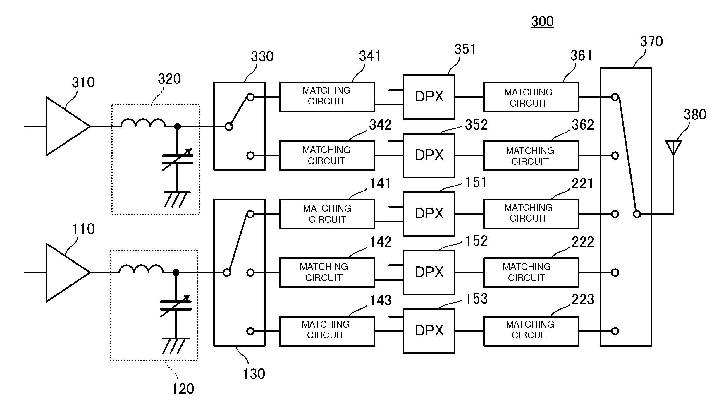
[0085]FIG. 8 is a diagram showing the configuration of a wireless communication high-frequency circuit 300 according to a third preferred embodiment of the present invention. This wireless communication high-frequency circuit 300 is a circuit including amplifiers that perform power amplification of a transmission signal to an antenna. The wireless communication high-frequency circuit 300 includes five duplexers 151, 152, 153, 351, and 352. Among these duplexers, the duplexers 151, 152, and 153 support the frequency range of the UMTS band 1, the UMTS band 2, and the UMTS band 3, respectively, and the duplexers 351 and 352 support the frequency range of UMTS band 5 and UMTS band 8, respectively.

[0086]The amplifier 110 performs the power amplification to the transmission signal at a certain gain across the frequency range of the UMTS band 1 to the UMTS band 3. An amplifier 310 performs the power amplification to the transmission signal at a certain gain across the frequency range of th...


PUM


Abstract

A wireless communication high-frequency circuit in which a broadband amplifier is shared between multiple communication frequency bands and multiple duplexers are used in order to support the multiple communication frequency bands to improve the transmission efficiency includes a first impedance matching circuit between an output port of an amplifier and a relay switch. A first signal path extends from the output port of the amplifier to the ground in the first impedance matching circuit. An inductor and a variable capacitance element are provided on the first signal path. Second impedance matching circuits are provided between output ports and the input port of the relay switch and transmission signal input ports of duplexers, respectively.

Description

BACKGROUND OF THE INVENTION[0001]1. Field of the Invention[0002]The present invention relates to a wireless communication high-frequency circuit using, for example, a mobile phone terminal and a wireless communication apparatus.[0003]2. Description of the Related Art[0004]Mobile phone terminals in recent years are generally capable of using multiple communication frequency bands. For example, Japanese Unexamined Patent Application Publication No. 2002-325049 discloses a communication terminal that uses both CDMA and TDMA and that is capable of handover between CDMA and TDMA.[0005]FIG. 1 is a diagram showing the system configuration of the communication terminal disclosed in Japanese Unexamined Patent Application Publication No. 2002-325049. The communication terminal mainly includes an antenna duplexer unit 2, a modulator-demodulator unit 4, a power amplifier unit 3, a signal processing unit 5, and a control unit 6. The modulator-demodulator unit 4 includes a TDMA modulator, a TDMA ...

Claims


Application Information

Patent Timeline
Patent Type & Authority Applications(United States)
IPC IPC(8): H04B7/00H01P1/10H04B1/04H04B1/3822H04B1/40
CPCH03F1/0277H04B1/406H03F3/189H03F3/24H03F3/72H03F2200/387H03F2200/391H03F2200/411H03F2200/414H03F2200/421H03F2200/429H03F2200/451H03F2203/7209H03F2203/7215H03F2203/7221H03F2203/7233H03F2203/7236H03H7/38H04B1/0067H04B1/0458H03F1/565
Inventor SHIBAHARA, TERUHISA
Owner MURATA MFG CO LTD
Why Eureka
Try Eureka