Vehicle control system and automobile

a technology for controlling systems and automobiles, applied in battery/fuel cell control arrangements, propulsion by capacitors, instruments, etc., can solve problems such as waste of electric energy stored therein, and achieve the effects of preventing the life of chemical storage units from being wastefully short, reducing the voltage of physical storage units, and reducing energy loss

Inactive Publication Date: 2012-04-12
PANASONIC CORP
View PDF5 Cites 21 Cited by
  • Summary
  • Abstract
  • Description
  • Claims
  • Application Information

AI Technical Summary

Benefits of technology

[0013]With the stated structure, the control unit controls the use of the electric power of the physical storage unit when the vehicle in which the vehicle control system is mounted approaches the parking position indicated by the parking position information piece. Accordingly, by the time the vehicle stops, the voltage of the physical storage unit is reduced. In general, the lower the remaining voltage of the physical storage unit is, the less likely self-discharge thereof is to occur and the smaller the amount of discharge thereof is. Therefore, self-discharge of the physical storage unit is less likely to occur after the vehicle stops, resulting in an energy loss being more efficiently suppressed than in the conventional technologies. Also, suppose that the electric power of the physical storage unit is used to charge the chemical storage unit. Even in such a case, the control of the use of the electric power of the physical storage unit is performed only when the vehicle approaches a predetermined parking position. This prevents charging from being performed every time the vehicle stops, thus preventing the life of the chemical storage unit from being wastefully shortened.

Problems solved by technology

In this case, for example, the remaining voltage of the electric double-layer capacitor decreases over time, resulting in the electric energy stored therein being wasted, as shown in FIG. 14.

Method used


Image

  • Vehicle control system and automobile
  • Vehicle control system and automobile
  • Vehicle control system and automobile

Examples


embodiment 1

[0029]

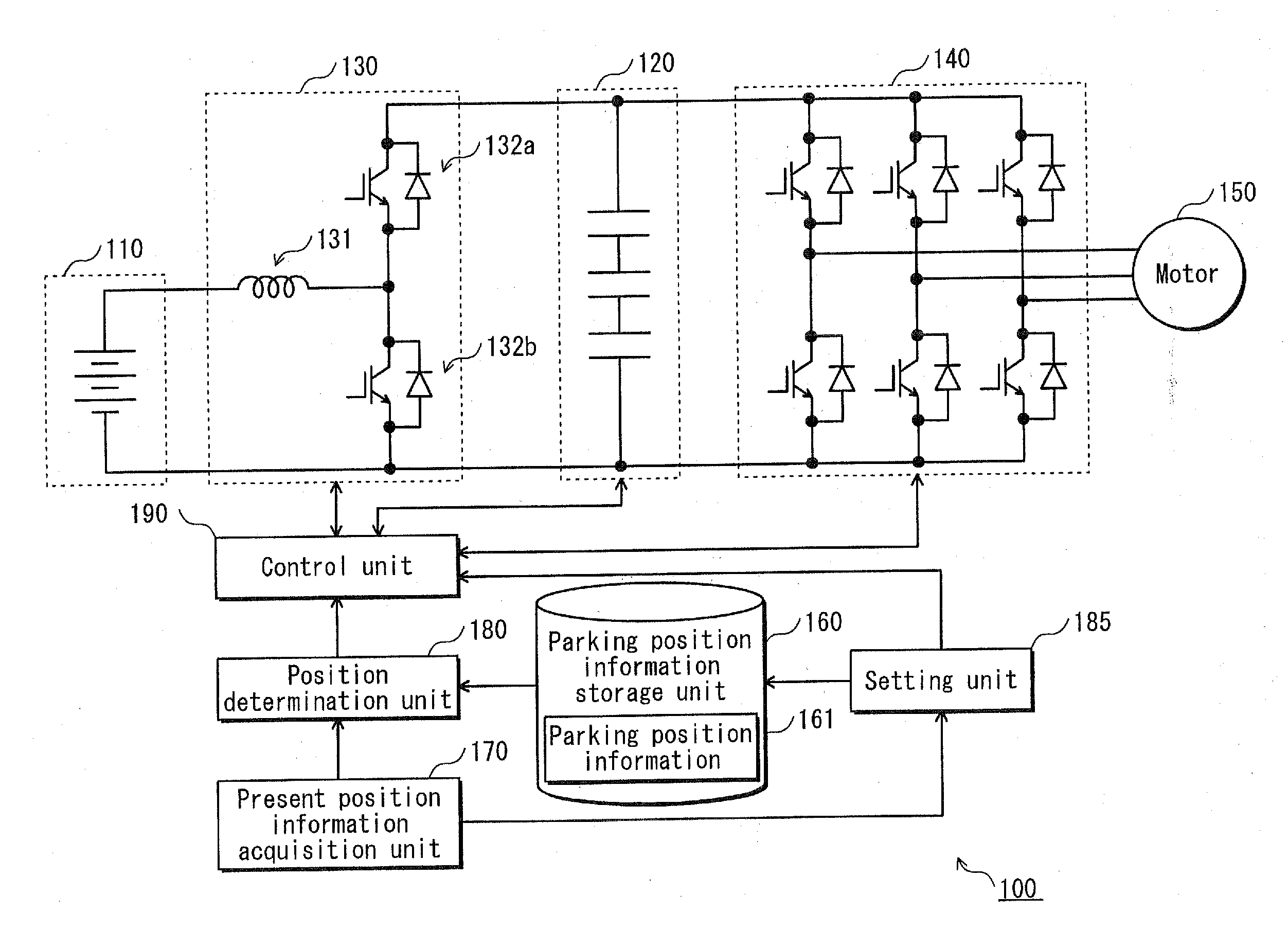
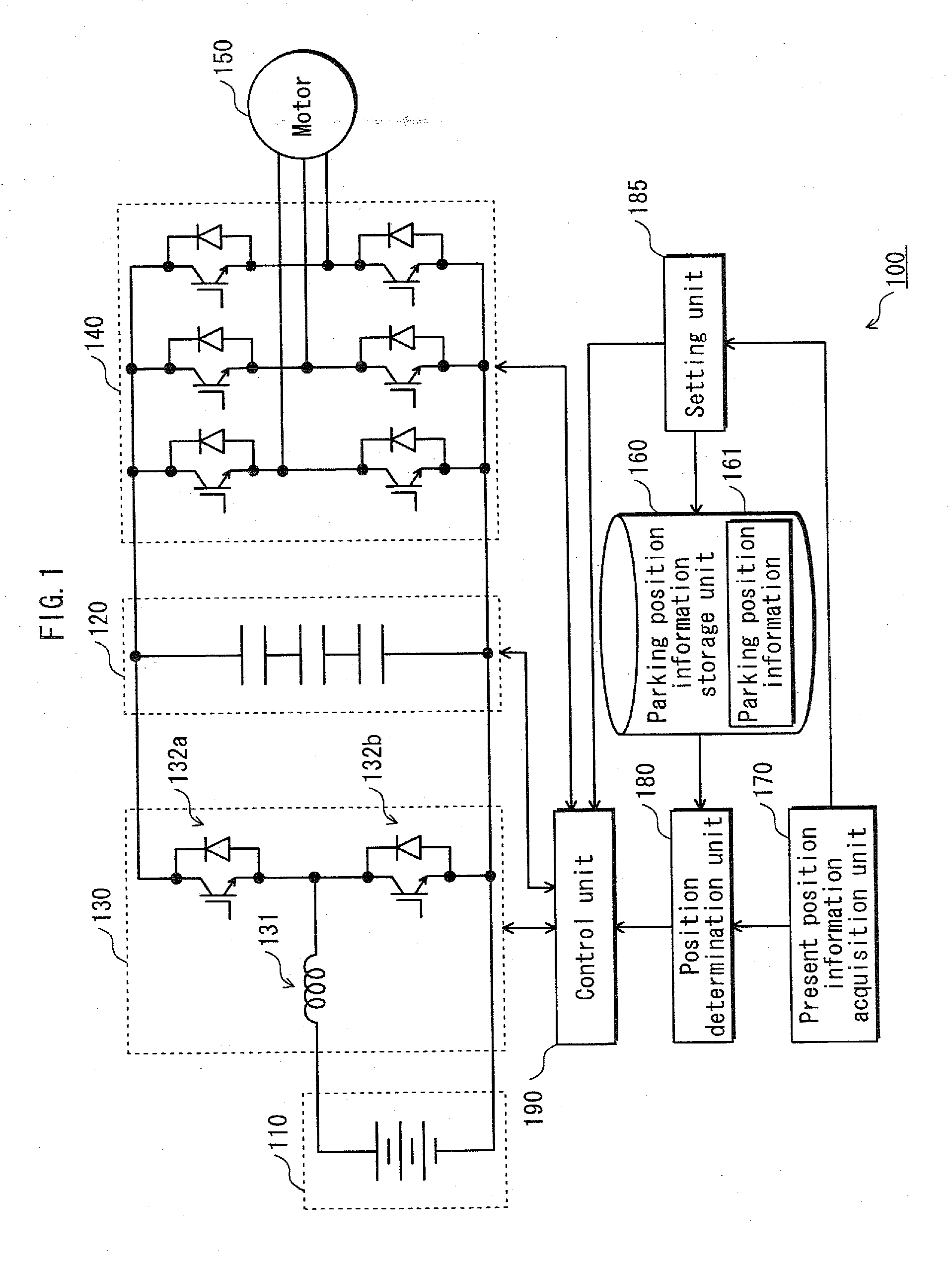
[0030]FIG. 1 shows the structure of a vehicle control system 100 according to Embodiment 1.

[0031]As shown in FIG. 1, the vehicle control system 100 includes a chemical storage unit 110, a physical storage unit 120, a charge and discharge circuit 130, an inverter 140, a motor 150, a parking position information storage unit 160, a present position information acquisition unit 170, a position determination unit 180, a setting unit 185, and a control unit 190.

[0032]The chemical storage unit 110 is a secondary battery that stores electric power by a chemical reaction, and is realized by a nickel hydride battery, a lithium-ion battery, a lithium polymer battery, or the like.

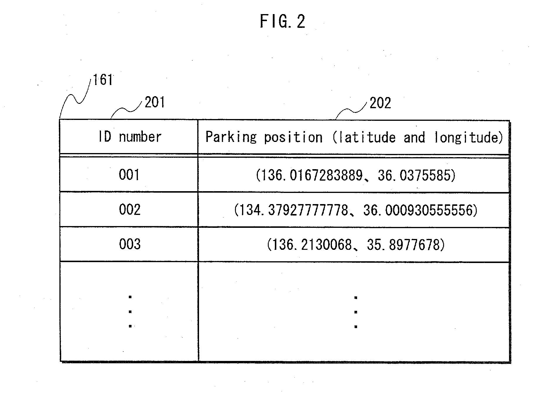
[0033]The physical storage unit 120 stores electric power by absorption and desorption of electrons and ions with respect to an electrode, and is realized by an electric double-layer capacitor or the like. The electric double-layer capacitor may be referred to as an ultracapacitor or a supercapacitor. In recent ...

embodiment 2

[0085]In Embodiment 2, a vehicle control system is disclosed that performs an operation equivalent to the vehicle control system described in Embodiment 1, and that has a different structure from the vehicle control system in Embodiment 1.

[0086]

[0087]FIG. 6 shows the structure of a vehicle control system 200 according to Embodiment 2.

[0088]As can be seen from the comparison between FIG. 6 and FIG. 1, the vehicle control system 200 is different from the vehicle control system 100 in that the chemical storage unit 110 is directly connected to the inverter 140 without a charge and discharge circuit 134 therebetween. Also, the vehicle control system 200 is different in that the physical storage unit 120 is connected to the low-voltage side of the charge and discharge circuit 134, and the chemical storage unit 110 is connected to the high-voltage side of the charge and discharge circuit 134.

[0089]Furthermore, the vehicle control system 200 includes a control unit 191, instead of the cont...

embodiment 3

[0099]Embodiment 1 discloses a method for supplying electric power (charging) from the physical storage unit to the chemical storage unit, as a usage pattern of the electric power of the physical storage unit. Embodiment 3 discloses another usage pattern of the electric power of the physical storage unit.

[0100]

[0101]FIG. 7 shows the structure of a vehicle control system 300 according to Embodiment 3.

[0102]As shown in FIG. 7, in addition to the structure of the vehicle control system 100 in Embodiment 1, the vehicle control system 300 further includes an air conditioner inverter 141 and an air conditioner motor 151, both of which are for use in an air conditioner. The inverter 141 is directly connected to the chemical storage unit 110.

[0103]Furthermore, the vehicle control system 300 includes a control unit 192, instead of the control unit 190 in Embodiment 1.

[0104]The air conditioner inverter 141 receives electric power from the chemical storage unit 110, generates an alternating cu...


PUM


Abstract

A vehicle control system includes: a chemical storage unit 110 such as a lithium ion battery; a physical storage unit 120 such as a capacitor; an inverter 140 that is driven upon receiving a direct current from the storage units 110 and 120; and a motor 150 that is driven upon receiving an alternating current output from the inverter 140. The vehicle control system comprises: a position determination unit 180 for determining, based on present position information acquired by a present position information acquisition unit 170, whether a vehicle is approaching a parking position indicated by parking position information 161; and a control unit 190 for, when the vehicle is determined to be approaching the parking position, controlling the use of the electric power of the physical storage unit 120, such as charging the chemical storage unit 110 with electric power from the physical storage unit 120.

Description

TECHNICAL FIELD[0001]The present invention relates to a vehicle control system for controlling a vehicle that moves by an electric motor with a storage battery being a main power source, and an automobile in which the vehicle control system is mounted.TECHNICAL FIELD[0002]In recent years, environmentally friendly automobiles, such as electric cars that move by the drive force of a motor, hybrid cars that move by the drive force of an engine and a motor, etc., have been a focus of attention. Such an automobile includes an electric storage mechanism including a secondary battery, an electric double-layer capacitor, and the like. The power of the secondary battery is stored in the electric double-layer capacitor, and the power of the electric double-layer capacitor is used for driving the motor. Also, at the time of a regenerative operation, the kinetic energy of the automobile is converted to an electric energy and stored in the electric double-layer capacitor. The discharge operation...

Claims


Application Information

Patent Timeline
Patent Type & Authority Applications(United States)
IPC IPC(8): G06F7/00
CPCB60L11/005B60L11/1868B60L2240/62B60W2550/402Y02T10/7005Y02T90/162Y02T10/7022Y02T10/7066Y02T10/7291Y02T90/16Y02T10/7011B60L50/40B60L58/20B60W2556/50Y02T10/70Y02T10/72
Inventor NAKATA, HIDEKI
Owner PANASONIC CORP
Why Eureka
Try Eureka