Synthetic bone grafts constructed from carbon foam materials

a carbon foam and synthetic bone technology, applied in the field of structural bone void fillers, can solve the problems of insufficient autologous bone available as a void filler, high failure rate, secondary trauma to the patient,

Active Publication Date: 2012-04-19
WICHITA STATE UNIVERSITY
View PDF9 Cites 11 Cited by
  • Summary
  • Abstract
  • Description
  • Claims
  • Application Information

AI Technical Summary

Benefits of technology

[0007]The present invention is broadly concerned with a porous, self-sustaining body useful as a scaffold for bone grafting. The porous, self-sustaining body comprises a carbonaceous matrix comprising a continuous phase having a surface and defining a plurality of open spaces throughout the matrix; and a coating adjacent the continuous phase surface of the matrix. The coating is selected from the group consisting of osteogenic materials, therapeutic agents, and combinations thereof. The porous body is substantially free of metals, and preferably other inorganic materials. In one or more embodiments, the matrix is formed of a carbonaceous material selected from the group consisting of carbon foam, graphitic foam, and combinations thereof.
[0008]In another aspect, there is provided a method of making a porous, self-sustaining body useful as a scaffold for bone grafting. The method comprises providing a carbonaceous matrix comprising a continuous phase having a surface and defining a plurality of open spaces throughout the matrix; and forming a coating adjacent the continuous phase surface of the matrix. The coating is selected from the group consisting of osteogenic materials, therapeutic agents, and combinations thereof. The porous body is substantially free of metals.
[0009]The invention is also concerned with a method of repairing or replacing in a subject a bone void hav

Problems solved by technology

However, in major traumatic injury, there is usually insufficient autologous bone available as a void filler.
In addition, harvesting of the graft from the donor site for bone autografts causes a secondary trauma to the patient.
This is avoided by the use of allografts and xenografts; however, these bone grafts require the use of immunosuppressives to avoid implant rejection by the patient, can transmit viruses, and have a relatively high failure rate.
However, current bone fillers are generally intended for use only in voids that are

Method used


Image

  • Synthetic bone grafts constructed from carbon foam materials
  • Synthetic bone grafts constructed from carbon foam materials
  • Synthetic bone grafts constructed from carbon foam materials

Examples


example 1

Initial Biornaterial Analysis for Mechanical Properties

[0061]Extensive studies into the development ofbiomaterials with a particular focus upon bone and nerve grafting using tissue engineered scaffolds were previously carried out on poly-epsilon-caprolactone-hydroxyapatite (PCL-HA) composites and chitosan-collagen composites. A number of model systems for the evaluation of bone biocompatibility were also developed previously. A novel PCL-HA composite was developed to promote vascularization of the bone graft substitute, as PCL has been approved by the FDA for use in medical and drug delivery devices, and studies have demonstrated its biocompatibility. However, its structural properties proved to be less than ideal for use as a bone void filler, and its degradation and resorption rates were too rapid to provide structural support during bone ingrowth. Thus, a series of preliminary studies were carried out on carbon foam scaffolds for bone grafting and regeneration.

[0062]Mechanical te...

example 2

In Vitro Biocompatibility of Carbon Foam

1. Initial Testing

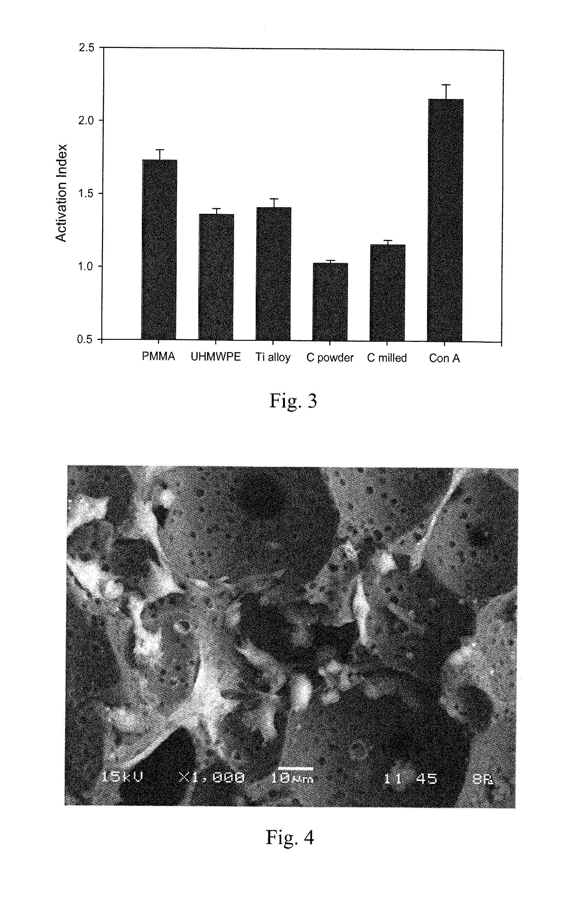
[0064]Initial biocompatibility of carbon foam was conducted using a cell culture system developed in our laboratory for the evaluation of patient hypersensitivity to orthopaedic biomaterials. Carbon in both powdered and milled fiber forms was evaluated using mononuclear cells (MNCs) obtained from 40 osteoarthritic patients under investigation for biomaterial sensitivity, along with other conventional biomaterials (polymethylmethacrylate (PMMA), Ti alloy, ultra-high-molecular-weight polyethylene (UHMWPE)). Peripheral blood was obtained from patients and MNCs were separated using Histopaque gradients. Cell suspensions of 2.5×10⁶ cells were dispensed into wells containing various concentrations of biomaterial particles. Wells with no particles (negative control) or with Concanavalin A (ConA) (positive control) were also included on the plate. Plates were incubated for 6 days. Next, 20 μl of MTT solution (5 mg / ml) were then to ea...

example 3

In Vivo Biocompatibility of Carbon Foam

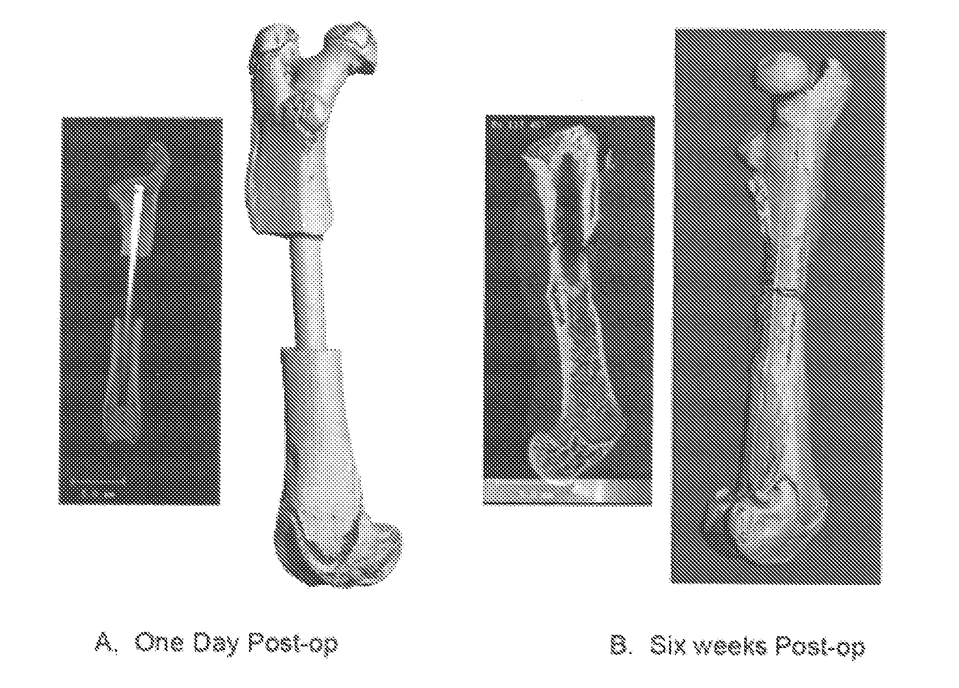
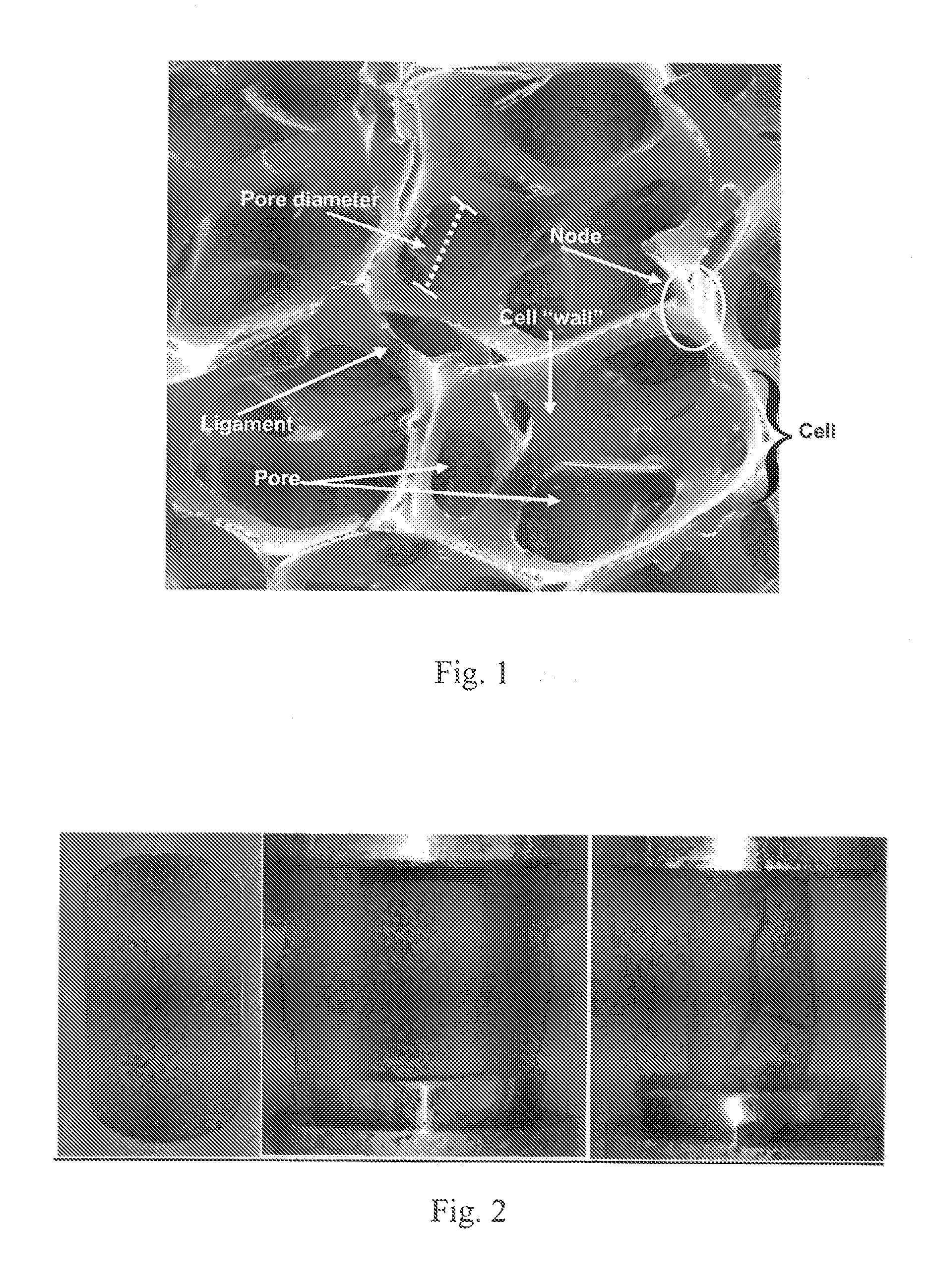
[0067]Initial in vivo testing of carbon foam scaffolds was carried out to further evaluate the material for biocompatibility and determine if cellular ingrowth within the porous structure could be readily achieved. Two forms of carbon (DUOCEL®) with widely disparate structural properties were selected for testing: (1) A closed cell carbon foam (pore size ˜120 μm); and (2) An open cell carbon foam (pore size ˜1 mm). Initial testing was conducted using a previously-developed murine air pouch implantation model (Wooley et al. Inflammatory responses to orthopaedic biomaterials in the murine air pouch. Biomaterials 2002; 23:517-526; and Ottaviani et al. Inflammatory and immunological responses to hyaluronan preparations. Study of a murine biocompatibility model. J Bone Joint Surg Am 2007; 89(1):148-157).

[0068]Balb / c mice weighing 20-25 g were divided into two implantation groups, and air pouches were established 6 days before carbon foam implantatio...


PUM

PropertyMeasurementUnit
Fractionaaaaaaaaaa
Timeaaaaaaaaaa
Timeaaaaaaaaaa

Abstract

A porous, self-sustaining body useful as a scaffold for bone grafting is provided. The scaffold comprises a carbonaceous matrix comprising a continuous phase having a surface and defining a plurality of open spaces throughout the matrix. The internal and external surfaces of the matrix are coated with a layer or film selected from the group consisting of osteogenic materials, therapeutic agents, and combinations thereof. The porous body comprises organic materials and is substantially free of metals. Methods of making and using the porous self-sustaining body are also provided, along with kits for facilitating the same.

Description

CROSS-REFERENCE TO RELATED APPLICATIONS[0001]The present application claims the priority benefit of U.S. Provisional Patent Application Ser. No. 61 / 392,789, filed Oct. 13, 2010, entitled Synthetic Bone Grafts Constructed from Carbon Foam Composite Materials, incorporated by reference in its entirety herein.BACKGROUND OF THE INVENTION[0002]1. Field of the Invention[0003]The present invention relates to organic bone void fillers comprising carbonaceous material for repairing bone voids, and particularly structural bone voids.[0004]2. Description of Related Art[0005]Bone is a regenerative tissue that can sometimes effectively repair fracture damage and small voids, but trauma that results in the loss of a large bone segment requires the use of a bone void filler to bridge the gap between bone segments. Bone void fillers are natural or synthetic materials placed into the bone defect to assist in bone regeneration and provide a three-dimensional structure to which bone tissue and cells c...

Claims


Application Information

Patent Timeline
IPC IPC(8): A61F2/28A61K36/04A61K31/765A61K35/32A61K33/42A61K35/14A61K48/00A61K39/395A61K38/43A61K38/02A61P19/08A61K35/12A61K9/00A61K31/711
CPCA61F2/28A61F2002/2835A61F2002/30011A61F2002/30062A61F2002/3092A61F2310/00161A61L2430/02A61F2310/00796A61F2310/0097A61L27/08A61L27/32A61L27/54A61L27/56A61F2310/00173A61F2310/00976A61P19/08A61L27/28A61L27/306A61L27/422
Inventor WOOLEY, PAUL HASTINGSYU, HAIYING
Owner WICHITA STATE UNIVERSITY
Why Eureka
Try Eureka