
Capacitive input test method

a technology of capacitive input and test method, which is applied in the field of capacitive input test method and system, can solve the problems of difficult measurement, even with very precise capacitors, and the linearity of the capacitive-to-digital converter, and achieve the effect of low throughput capacitan

Active Publication Date: 2012-04-26
IDT EURO GMBH
View PDF4 Cites 6 Cited by
  • Summary
  • Abstract
  • Description
  • Claims
  • Application Information

AI Technical Summary

Benefits of technology

[0009]Additional features and advantages are realized through the techniques of the present invention. Other embodiments and aspects of the invention are described in detail herein and are considered a part of the claimed invention.

Problems solved by technology

However, a difficulty arises when attempting to measure, even with very precise capacitors, the linearity of the capacitive-to-digital converter.

Method used


Image

  • Capacitive input test method
  • Capacitive input test method
  • Capacitive input test method

Examples


Embodiment Construction

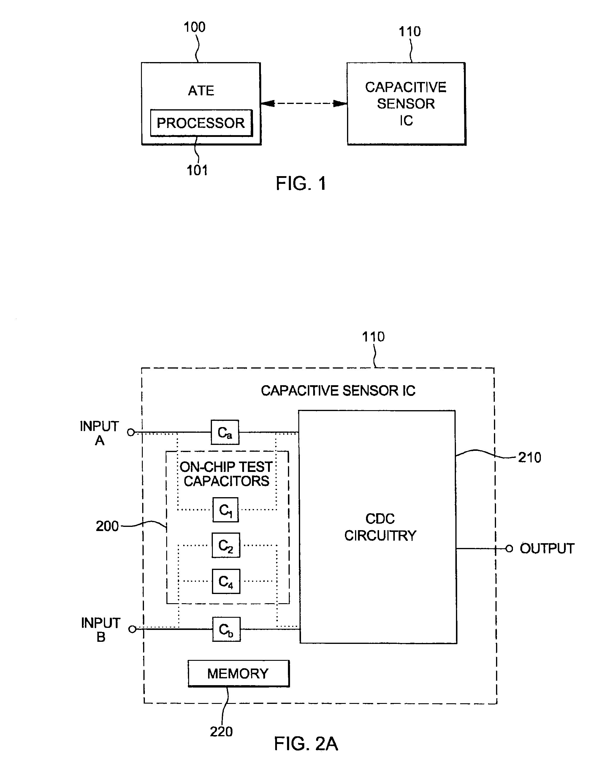
[0017]FIG. 1 depicts an automated test equipment (ATE) system 100 coupled to a capacitive sensor integrated circuit (IC) chip 110 to be tested, in accordance with one or more aspects of the present invention. As illustrated, ATE system 100 includes a processor 101 which may, in one embodiment, implement one or more processing steps described herein below. Alternatively, one or more of the processing steps described herein may be implemented by a processor (not shown) embedded within capacitive sensor IC chip 110.

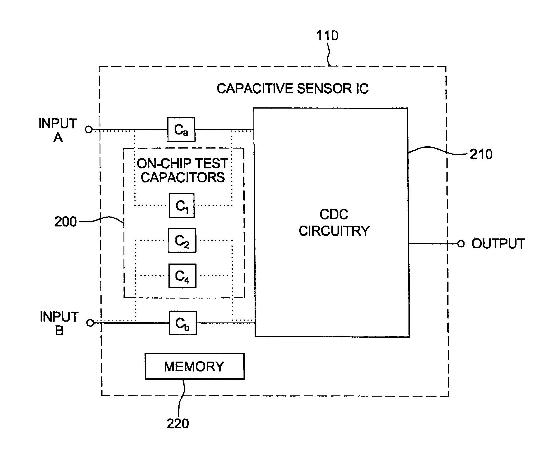
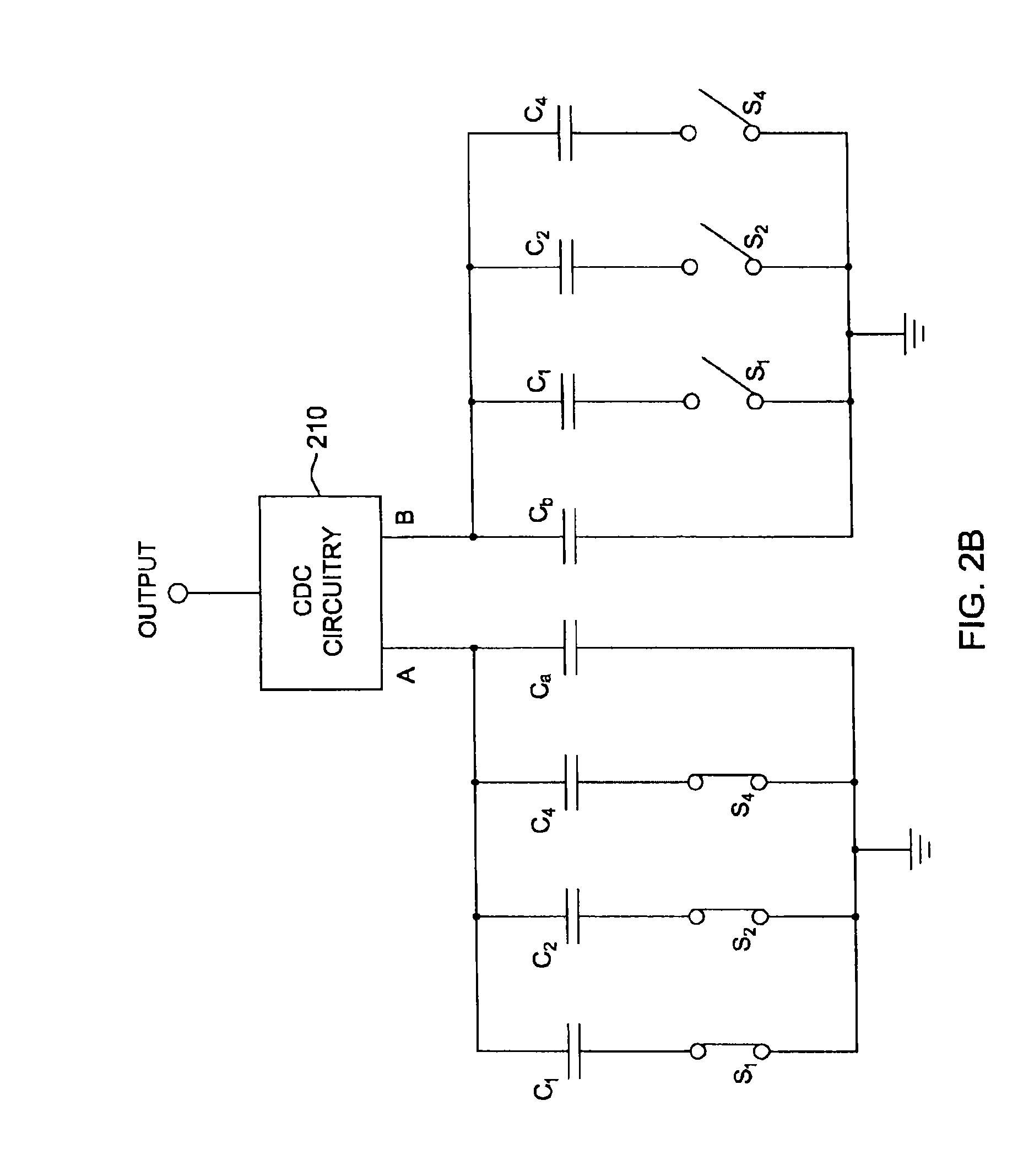
[0018]As illustrated in FIG. 2, linearity measurement is facilitated, in one embodiment, by a set of on-chip test capacitors 200 disposed to be selectively switched (during chip testing) in parallel with either a first input A or a second input B of the capacitance-to-digital converter (CDC) circuitry 210. In the example illustrated in FIG. 2A, an on-chip capacitor C1 is switched in parallel with parasitic capacitance Ca of first input A, and second and third on-chip capacit...


PUM


Abstract

Method and system are provided for evaluating linearity of a capacitive-to-digital converter (CDC) of a capacitive sensor integrated circuit chip. The evaluating employs multiple test capacitors, which may be on-chip with the CDC, and includes: obtaining capacitance values for the multiple test capacitors and parasitic capacitances of a first input A and a second input B to the capacitive-to-digital converter; applying the multiple test capacitors in multiple permutations to the first input A and the second input B, and for each of at least some permutations, determining an error between an expected output of the CDC using the obtained capacitance values and an actual measured output of the CDC; and determining linearity error for the CDC using the determined errors for the permutations of applying the multiple test capacitors to the first input A and the second input B of the CDC.

Description

CROSS-REFERENCE TO RELATED APPLICATION[0001]This application claims the benefit of U.S. Provisional Application No. 61 / 143,846, filed Jan. 12, 2009, which is hereby incorporated herein by reference in its entirety.BACKGROUND[0002]The present invention relates in general to testing of electronic devices such as Complementary Metal-Oxide-Semiconductor (CMOS) devices, and more particularly, to a capacitive input test method and system for accurate testing of capacitance-to-digital conversion of a capacitive sensor signal.[0003]Capacitive sensor signal-conditioning integrated circuits, such as the cLite™ capacitive sensor signal conditioner (or cLite™ ASSP (Application Specific Standard Product)) available from Zentrum Mikroelektronik Dresden (ZMD) AG of Dresden Germany, comprise a capacitive-to-digital converter and are able to convert a capacitance within a selectable range (for example, 2-260 pF in the case of the cLite™ signal conditioner), to a corresponding digital value. Advantag...

Claims


Application Information

Patent Timeline
IPC IPC(8): G01R31/3187
CPCH03M1/12H03M1/109
Inventor KRAUSS, MATHIASKOBLENSKI, SAM
Owner IDT EURO GMBH
Learn More