Ring oscillator and control method of ring oscillator

a control method and oscillator technology, applied in the direction of pulse automatic control, pulse generation by logic circuits, pulse techniques, etc., can solve the problems of low operating bandwidth of oscillators, low linearity, and low frequency response, and achieve continuous adjustment of the loading of each ring stage, wide adjustable frequency range, and high linearity

Inactive Publication Date: 2012-04-26
UNITED MICROELECTRONICS CORP
View PDF2 Cites 5 Cited by
  • Summary
  • Abstract
  • Description
  • Claims
  • Application Information

AI Technical Summary

Benefits of technology

[0012]The present invention provides a ring oscillator with high linearity and adjustable frequency. Via controlling a bias current of the ring oscillator, the goal of controlling a frequency of an output signal non-continuously can be achieved. In addition, the present invention simultaneously utilizes a voltage controlled variable cap

Problems solved by technology

For an oscillator, linearity, operational bandwidth, phase noise and gain (i.e., Kvco) will have great influence on the overall performance, however, the aforementioned parameters usually interfere with each other, therefore during the design process, a balance point should be compromised in consideration of all parameters according to different requirements.
For example, since a control signal for control an output frequency is usually limited by supply voltage, the operational bandwidth is substantially proportional to the gain (the operational bandwidth equals to a product of control signal var

Method used


Image

  • Ring oscillator and control method of ring oscillator
  • Ring oscillator and control method of ring oscillator
  • Ring oscillator and control method of ring oscillator

Examples


first embodiment

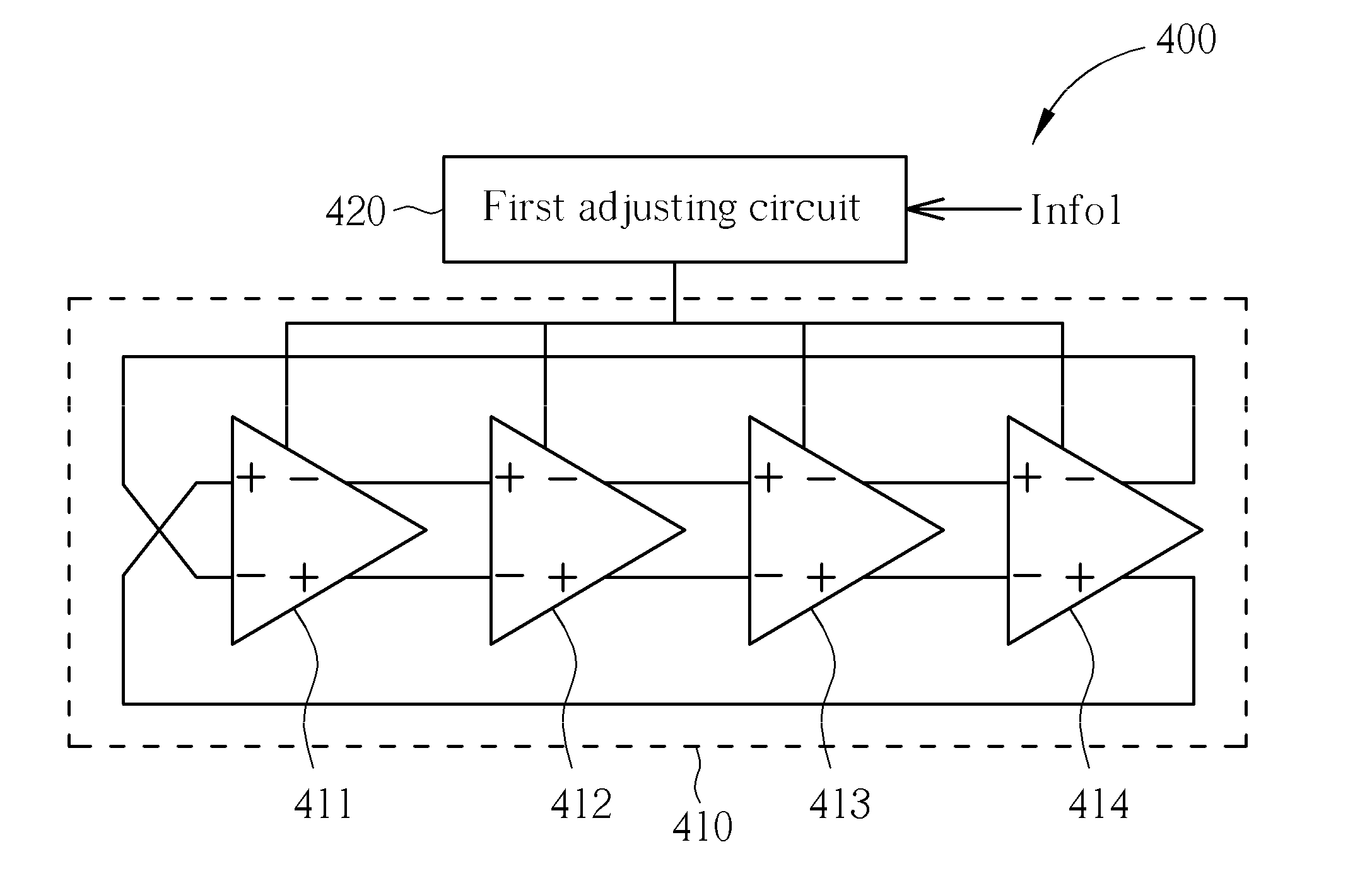
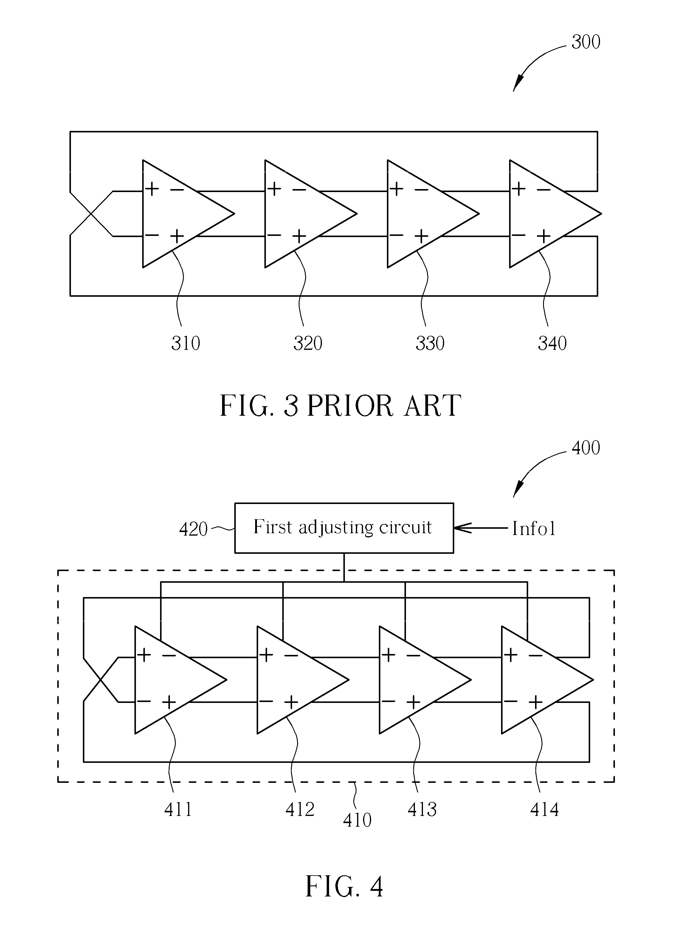
[0029]Please refer to FIG. 4, which is a diagram of a ring oscillator 400 according to the present invention. In this embodiment, the ring oscillator 400 includes (but not limited to) a core circuit 410 for outputting a clock signal and a first adjusting circuit 420. In addition, the core circuit 410 includes four differential ring stages 411, 412, 413 and 414; however, the aforementioned structure of the ring oscillator 400 is for illustrative purpose only. In other embodiments, the ring oscillator 400 may also be implemented by single-ended ring stages, and the number of the ring stages is not limited as well. As shown in the figure, in the core circuit 410, each ring stage includes an output terminal (−,+) and an input terminal (+,−), where the output terminal (−,+) is coupled to the input terminal (+,−) of a next ring stage, and the input terminal (+,−) is coupled a previous output terminal (−,+). The first adjusting circuit 420 is for receiving a plurality of first control info...

second embodiment

[0035]Regarding the circuit structure shown in FIG. 4, the first adjusting circuit 420 provides a mechanism of altering the gain of each ring stage in the ring oscillator 400, so as to adjust a frequency of the clock signal generated by the core circuit 410. However, the first adjusting circuit 420 only provides a mechanism of adjusting the clock signal frequency of the ring oscillator 400 non-continuously, to adjust the frequency of the clock signal more accurately, the present invention further provides another fine-tune mechanism. Please refer to FIG. 8, which is a diagram of a ring oscillator 800 according to the present invention. The ring oscillator 800 includes (but not limited to) a core circuit 810 for outputting a clock signal, a first adjusting circuit 820, and a second adjusting circuit 830. The function and structure of the core circuit 810 and the first adjusting circuit 820 are substantially identical to the core circuit 410 and the first adjusting circuit 420 shown i...

third embodiment

[0039]The aforementioned embodiments are for illustrative purpose only, and the adjusting circuits therewithin can be utilized independently or combined together. For example, please refer FIG. 13, which is a diagram of a ring oscillator 1300 according to the present invention. The ring oscillator 1300 includes a current source IB, a core circuit 1310 and an adjusting circuit 1330, wherein the current source IB is for providing a constant bias current to the core circuit 1310, the function and structure of the core circuit 1310 and the adjusting circuit 1330 are substantially identical to the core circuit 810 and the second adjusting circuit 830 shown in FIG. 8, and the adjusting circuit 1330 will adjust a loading of each ring stage in the core circuit 1310 according to control information Info, thereby controlling a frequency of a clock signal generated from the ring oscillator 1300. However, for ring oscillator 1300, the adjusting circuit 1330 is utilized to continuously adjust th...


PUM


Abstract

A ring oscillator including a core circuit and a first adjusting circuit. The core circuit is for outputting a clock signal, and includes a plurality of ring stages. The first adjusting circuit is for receiving a plurality of first control information, and referring to the plurality of first control information to adjust the clock signal. The first adjusting circuit includes a plurality of bias circuits and a plurality of switch elements. The bias circuits are for providing a plurality of currents, and the switches are connected to the bias circuits in series and receive the plurality of first control information, respectively, wherein each switch element is selectively conducting according to a corresponding first control information for determining whether a current provided by a corresponding bias circuit is utilized to bias the core circuit.

Description

BACKGROUND OF THE INVENTION[0001]1. Field of the Invention[0002]The present invention relates to a clock generating circuit, and more particularly, to a ring oscillator.[0003]2. Description of the Prior Art[0004]Oscillators are generally used in electronic systems to provide stable clock signals. Among various architectures of oscillators, ring oscillator is often utilized in many system chips due to its simple structure and easy implementation.[0005]However, a ring oscillator is generally constructed by multiple ring stages connected in a ring, where each ring stage is an inverse amplifier and an input signal at the input node of the inverse amplifier will be amplified at the output node of the inverse amplifier after a certain delay time, thereby generating an output signal of the ring stage. After traveling through a positive feedback loop consisting of all the ring stages, the input signal will vary its voltage level continuously and thereby turn out to be an oscillating signal....

Claims


Application Information

Patent Timeline
IPC IPC(8): H03K3/03
CPCH03K3/011H03K3/0322H03L7/0995H03K2005/00202H03K2005/00065
Inventor LEE, GUO-HAU
Owner UNITED MICROELECTRONICS CORP
Why Eureka
Try Eureka