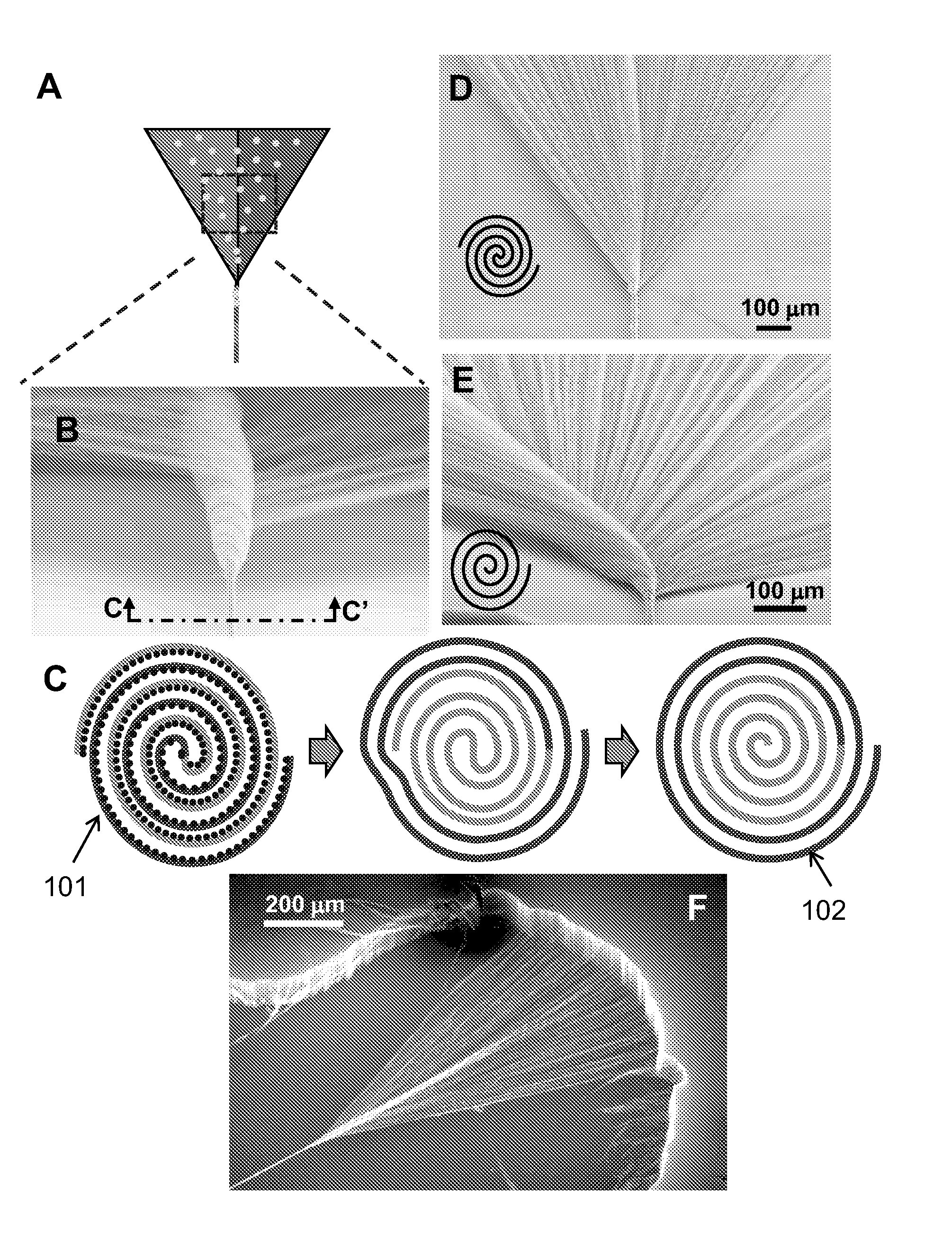
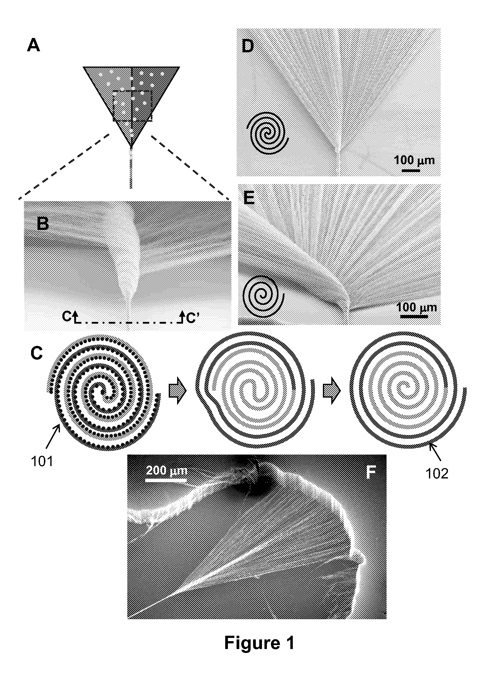
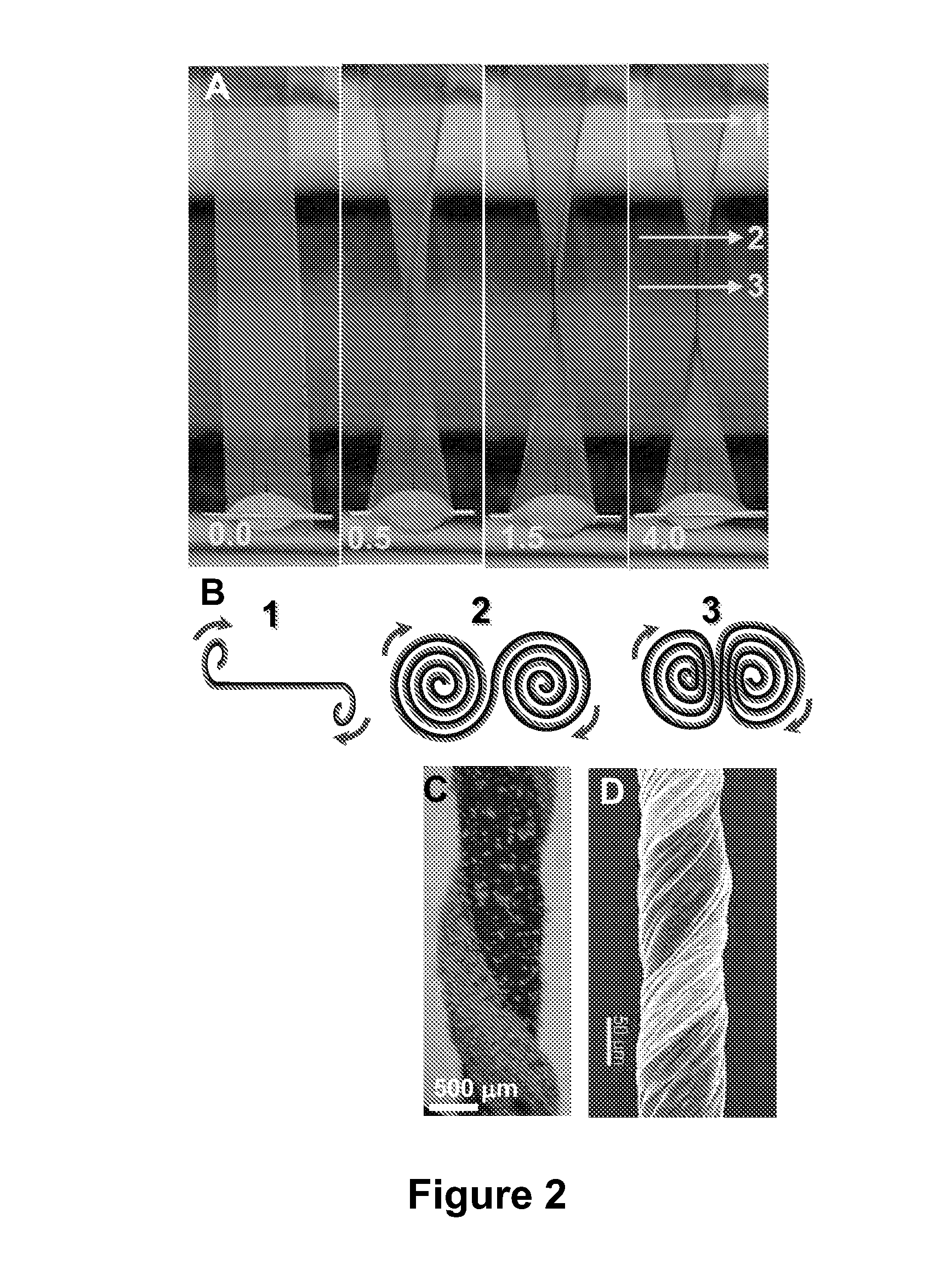
Fabrication of Biscrolled Fiber Using Carbon Nanotube Sheet

a technology of carbon nanotubes and biscrolled fibers, which is applied in the direction of catalyst activation/preparation, metal/metal-oxide/metal-hydroxide catalysts, metal/metal-oxide catalyst activation/preparation, etc., can solve the problems of reducing the loading level and durability, the functionality of nanopowder and nanofibers is often degraded, and the multi-functional materials are unspinnable. , to achieve the effect o

Active Publication Date: 2012-04-26
BOARD OF RGT THE UNIV OF TEXAS SYST
View PDF1 Cites 57 Cited by
  • Summary
  • Abstract
  • Description
  • Claims
  • Application Information

AI Technical Summary

Benefits of technology

[0039]The step of depositing particle material can include profiling distribution of the particle material. The step of profiling the distribution of the particle material can include preferentially positioning the particle material on one side of the sheet platform. The step of preferentially positioning the particle material can result in preferential distribution of the particle material in either the core or shell of the biscrolled yarn. The step of profiling the distribution of the particle material can include preferentially locating the particle material to increase accessibility of light to the particle material. The step of preferentially locating the particle material can allow the biscrolled yarn to be operable for a function of a dye-based electrochemical solar cell, light enabled textile cleaning, destruction of a biological threat, destruction of a chemical threat, or a combination thereof. The particle material can include TiO2.
[0043]The particle material can include high surface carbon materials obtained by reaction of carbides. The biscrolled yarn can be operable as a supercapacitor yarn.

Problems solved by technology

Despite important advances, critical problems remain: (1) most multifunctional materials are unspinnable using known technologies, (2) nanopowder and nanofiber functionality often degrades when accessible surface area decreases during processing, and (3) coating nanoparticles or nanofibers on yarns after yarn spinning can severely decrease loading levels and durability.
A problem hindering the applications of these powder materials is the need for methods for converting these powder (or nanoparticles or nanofibers) into yarns with ultra-high loading of the powder component to effectively utilize the properties of the powder materials.

Method used


Image

  • Fabrication of Biscrolled Fiber Using Carbon Nanotube Sheet
  • Fabrication of Biscrolled Fiber Using Carbon Nanotube Sheet
  • Fabrication of Biscrolled Fiber Using Carbon Nanotube Sheet

Examples


example 1

[0203]This Example 1 demonstrates the biscrolling process using solution deposition of guest MWNTs on host CNT sheets that are orthogonal. Though the sheets comprise MWNTs, the sheet nanofibers of the host are called CNTs in this example in order to avoid confusion with the solution deposited guest MWNTs. As illustrated in FIG. 5A, to prepare the free-standing CNT sheet stack, CNT sheets 501 were placed onto a wireframe 502. To prevent collapse of the sheets during solution deposition of MWNT suspension, two layers of the host CNT sheets were placed in the orthogonal direction relative to other layers of host sheets. Suspension of MWNT powder was prepared in ethanol and then deposited onto CNT sheet stack using a pipette. FIG. 5B illustrates the deposited MWNT powder 503 on the CNT sheet stack. After evaporating the solvent, a thin layer of the guest MWNTs was formed on the host CNT sheet stack.

[0204]To increase the thickness of the guest MWNT layer, several layers of guest MWNTs we...

example 2

[0205]This Example 2 describes the biscrolling process using electrophoretic deposition (EPD), which can deposit a large variety of guest materials onto the solid-state-spun CNT sheets. FIG. 6 schematically illustrates such a process of electrophoretic deposition. Although the deposition of nanoparticles over metals through electrophoresis has already been studied [R. Krupke et al., Adv. Mater. 18, 1468 (2006); A. K. Pal et al., Thin Solid Films 476, 288-294 (2005); P. Poulin et al., Carbon 40 1741-1749 (2002); S. K. Kim et al., J. Nanosci. Nanotechnol. 6, 3614-3618 (2006); and A. R. Boccaccini et al., Carbon 44, 3149-3160 (2006)], it is believed that this is the first demonstration of electrodeposition of nanoscale material onto CNT sheets.

[0206]Utilizing the mechanical strength of the sheet, this process makes possible the fabrication of free-standing sheets or ribbons mostly consisting of nanoparticles that cannot be easily assembled into yarns. The technology also enables a cont...

example 3

[0214]This Example 3 describes the biscrolling process using filtration-based deposition. In this process, the guest material to be deposited was dispersed in a suitable liquid medium using ultrasonication. Surfactants are sometimes used as the dispersing medium apart from the most commonly used mediums viz. de-ionized water and isopropanol. The filter for filtration deposition was a stack of MWNT sheets placed on a cellulose nitrate filtration membrane (Whatman, pore size was 0.45 μm, approximate thickness of 120 micrometers). Multiple layers of the MWNT sheets, typically one to three layers, were placed on the filter membrane, and then densified by wetting with isopropanolError! Reference source not found. The suspension of the guest material was then deposited onto the MWNT sheets / membrane through filtration. The filtration deposition of well dispersed suspensions formed a homogenous layer of the guest material on top of the membrane. After the filtration, the guest / MWNTsheet / fil...


PUM

PropertyMeasurementUnit
weight percentaaaaaaaaaa

Abstract

Fabrication of yarns or other shaped articles from materials in powder form (or nanoparticles or nanofibers) using carbon nanotube / nanofiber sheet as a platform (template). This includes methods for fabricating biscrolled yarns using carbon nanotube / nanofiber sheets and biscrolled fibers fabricated thereby.

Description

CROSS-REFERENCE TO RELATED PATENT APPLICATION[0001]This application for patent claims the benefit of priority from U.S. Provisional Patent Application Ser. No. 61 / 181,601, filed May 27, 2009, entitled “Fabrication of Biscrolled Fiber Using Carbon Nanotube Sheet,” which provisional patent application is commonly assigned to the assignee of the present invention, and which disclosure is considered part of and is incorporated by reference in its entirety in the disclosure of this application.GOVERNMENT INTEREST[0002]This work was supported by Air Force Office of Scientific Research grant FA9550-09-1-0384, Office of Naval Research MURI grant N00014-08-1-0654, Air Force Grant AOARD-10-4067, NSF grant DMI-0609115, and Robert A. Welch Foundation grant AT-0029. The U.S. government may have certain rights in the invention.FIELD OF INVENTION[0003]The present invention is related to fabrication of fibers (yarns) or other shaped articles from materials in powder form (or nanoparticles or nanofi...

Claims


Application Information

Patent Timeline
Patent Type & Authority Applications(United States)
IPC IPC(8): A61K9/70B01J37/02B01J21/06B01J35/06H01B1/00B05D5/12H01L39/24H01L39/02D02G3/00C12N5/07C01B13/02B82Y5/00B82Y40/00
CPCH01M4/131Y10T428/2929H01M4/1391H01M4/1393H01M4/5825H01M4/587H01M4/96H01M8/00H01M10/0525D02G3/16D10B2101/122A61L15/18A61L17/04A61L2300/108A61L2300/418A61L2400/12Y02E60/122Y02E60/50D01F9/12H01M4/133Y02E60/10Y10T428/2918A61K9/7007A61L31/024A61L31/16A61L2300/414B01J21/063B01J21/18B01J21/185B01J23/42B01J35/0006B01J35/004B01J35/06B01J37/0215B01J37/0238B05D3/12B05D5/00C23C14/04C23C14/58C23C16/04C23C16/56H01B12/06H01G11/86H01M4/04H01M4/0402
Inventor FANG, SHAOLILIMA, MARCIO DIASLEPRO-CHAVEZ, XAVIER N.CARRETERO-GONZALEZ, JAVIERCASTILLO-MARTINEZ, ELIZABETHOVALLE-ROBLES, RAQUELHAINES, CARTER SEBASTIANNOVITSKI, DAVID MICHAELHAQUE, MOHAMMAD H.LEWIS-AZAD, CHIHYEKOZLOV, MIKHAILZAKHIDOV, ANVAR A.BAUGHMAN, RAY H.
Owner BOARD OF RGT THE UNIV OF TEXAS SYST
Why Eureka
Try Eureka