Vehicular battery pack

a battery pack and battery technology, applied in the direction of battery/fuel cell control arrangement, instruments, electrochemical generators, etc., can solve the problems that the battery life may be substantially affected by a charge method, and achieve the effect of accurate prediction of battery life and battery trouble, time/suitable battery pack maintenance, and longer battery li

Inactive Publication Date: 2012-04-26
DENSO CORP
View PDF6 Cites 56 Cited by
  • Summary
  • Abstract
  • Description
  • Claims
  • Application Information

AI Technical Summary

Benefits of technology

[0013]According to the above configuration, by transmitting the degradation index of the battery to the responsible organization from an “intelligent” battery pack, the responsible organization such as a battery manufacturer, for example, is enabled to perform a battery life analysis and/or a trouble prediction analysis, thereby enabling a timely/suitable maintenance of the battery pack. Further, the responsible organization is enabled to accurately predict the battery life and the battery trouble.
[0014]According to the present disclosure, wherein the control unit performs the quick charge upon acquiring a quick charge request from a user of the vehicle, even when t

Problems solved by technology

However, when the battery pack is used in a vehicle as its driving power source, the battery life may substantially be affected by

Method used


Image

  • Vehicular battery pack
  • Vehicular battery pack
  • Vehicular battery pack

Examples


first embodiment

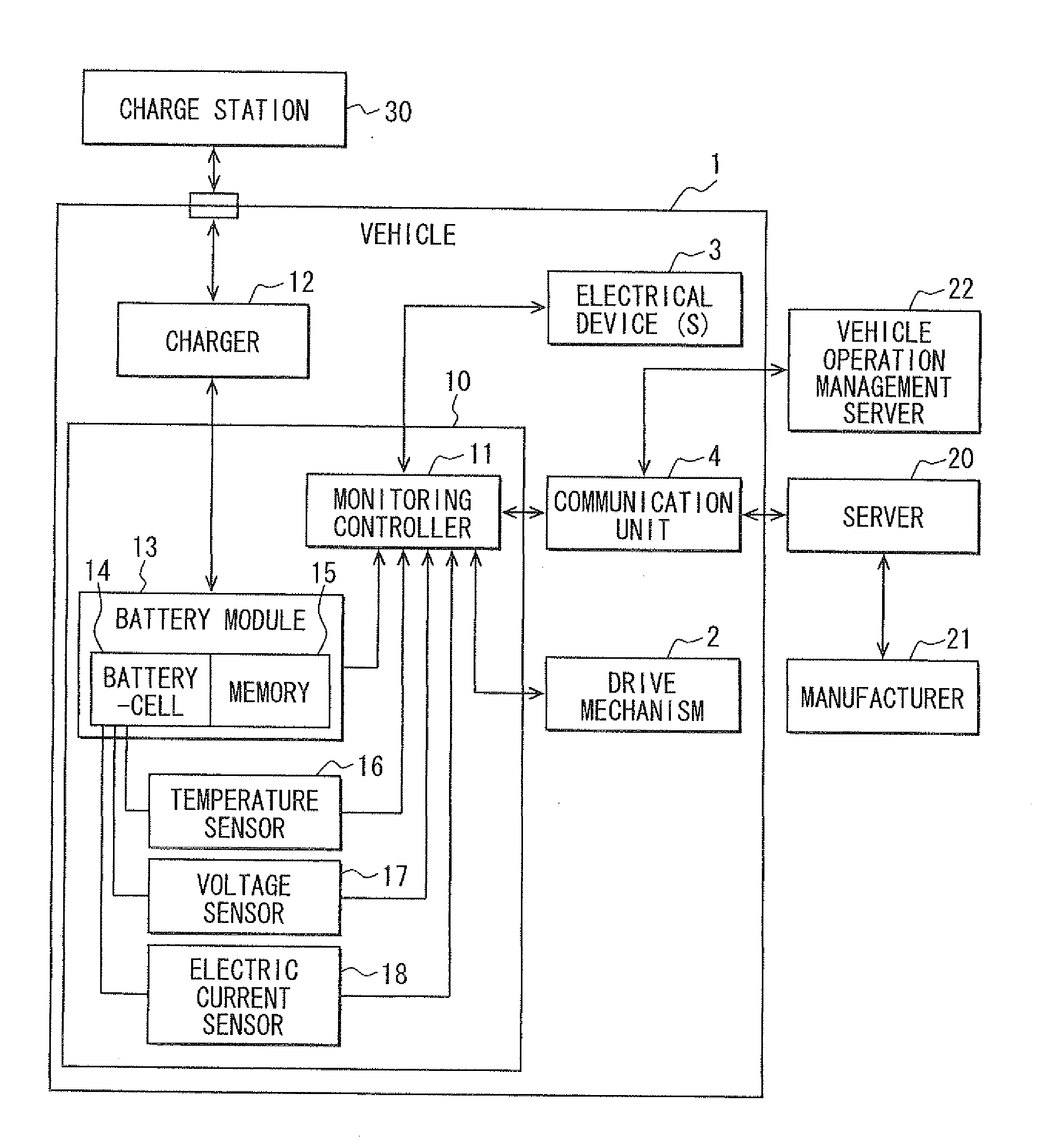
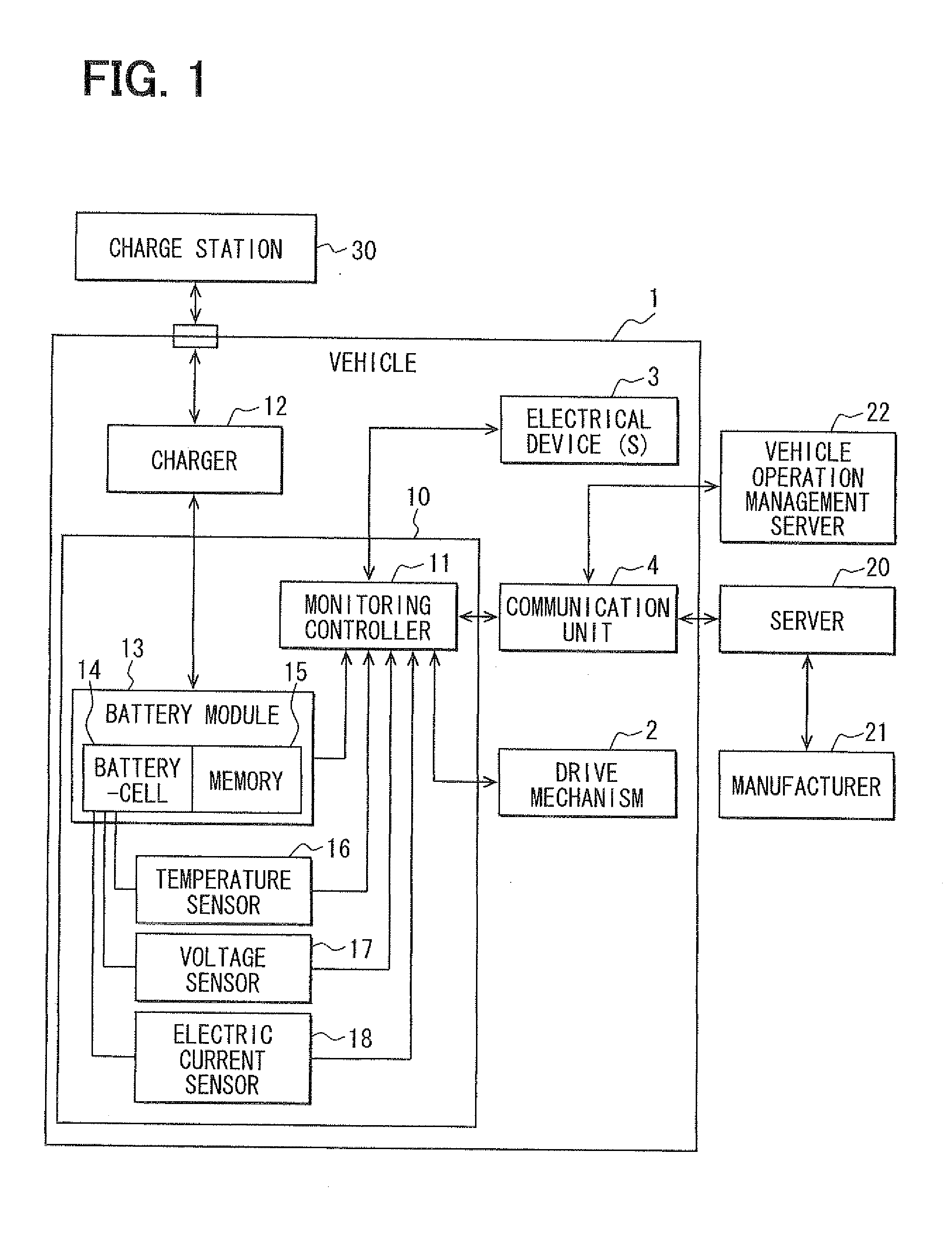
[0023]With reference to FIG. 1, a block diagram of a vehicle 1 that includes a battery pack 10 is shown. The vehicle 1 may be an electric vehicle that is powered by an electric motor or it may be a hybrid vehicle powered by both an electric motor and an internal combustion engine.

[0024]The battery pack 10 includes a plurality of battery modules 13 where each battery module 13 includes a battery cell 14 and a memory unit 15. The battery modules 13 are replaceable. The battery cell 14 is a basic component as the battery. For example, the battery cell 14 may be a lithium ion battery. In addition, the battery cell 14 and the memory 15 are structured to be inseparable without breaking the battery module 13.

[0025]The battery pack 10 further includes a temperature sensor 16 that measures the temperature of the battery cell 14, a voltage sensor 17 that measures the output voltage of the battery cell 14, an electric current sensor 18 that measures an electric current of the battery cell 14 w...

second embodiment

[0056]FIGS. 5 and 6 are used to explain the second embodiment, which is characterized by a different charge control than the charge control of the first embodiment. FIG. 5 is a flowchart of a control procedure performed at the time of charging the battery pack 10 in the second embodiment, and FIG. 6 is an illustration of a vehicle reservation table managed by a vehicle operation management server 22. Further, the battery pack 10, which performs the process of the second embodiment, has the same configuration as the first embodiment, as shown in FIG. 1, and has the same advantageous effects as the first embodiment.

[0057]The characteristic charge control described in the present embodiment performs, in addition to the charge control of the first embodiment, a useful charge control that handles an irregular use of the vehicle, which is not predictable from the charge-discharge history.

[0058]Each step of the flowchart in FIG. 5 is performed by the monitoring controller 11 of the battery...


PUM


Abstract

A battery pack includes a battery module that charges and discharges electricity to be used to drive a vehicle, and a monitoring controller for monitoring charge of the battery module. The monitoring controller stores past charge records and past discharge records in a charge-discharge history. Based on an analysis of learning data of a charge-discharge cycle in the charge-discharge history, the monitoring controller determines a charge operation, which may either be a normal charge or a quick charge, for charging the battery. The normal charge provides a charging electric current per unit time that is less than the charging current per unit time of the quick charge.

Description

CROSS REFERENCE TO RELATED APPLICATION[0001]The present application is based on and claims the benefit of priority of Japanese Patent Application No. 2010-236741, filed on Oct. 21, 2010, the disclosure of which is incorporated herein by reference.FIELD OF THE DISCLOSURE[0002]The present disclosure generally relates to a vehicular battery pack comprising batteries that are chargeable and dischargeable.BACKGROUND INFORMATION[0003]A conventional technique of charging a vehicular battery, is disclosed in Japanese Patent 2007-221900 (JP '1900). The technique disclosed in JP '1900 accurately manages a battery life of an intelligent battery pack that is equipped with a microcomputer and various sensors, based on monitoring the charge-discharge conditions and / or the number of re-charge times of the battery, Further, the battery packs used in a notebook computer (i.e. a note PC hereinafter) and the like regularly transmit various kinds of data to a management server in a battery management c...

Claims


Application Information

Patent Timeline
IPC IPC(8): G06F19/00
CPCH01M10/48H02J7/042H02J2007/0098B60L11/185B60L11/1851G06Q10/02Y02T90/121G06Q30/0645Y02T10/7005Y02T10/705Y02T90/14Y02T90/128G06Q10/087Y02T10/7072B60L53/11B60L58/10H01M10/4257H02J7/007Y02T10/70Y02E60/10H02J7/04Y02T90/12
Inventor HIRASAWA, HIDEFUMI
Owner DENSO CORP
Why Eureka
Try Eureka