[0008]The present invention overcomes the above limitations, and provides additional advantages over conventional head mounted displays. The present invention provides a virtual
retinal display that is consistent with natural
eye function. It provides high-resolution vision over a
large field of view combined with low bandwidth requirements. The head mounted portion of the present invention is lightweight, compact and ergonomic. It can properly display 3D imagery.
[0010]As explained in the Background section, achieving both
high resolution and a
wide field of view simultaneously is very difficult in head mounted displays. If this was achieved by simply filling a large pixel count flat-panel array (e.g.
liquid crystal displays or organic
light emitting diode arrays) with high-resolution imagery, the computational power required to drive the display would be largely wasted because high-resolution is useful to the eye only in the foveal region where it is currently looking, and everywhere else only a reduced resolution is required. Applicants break up the displayed imagery into a high-resolution foveal component and reduced resolution
peripheral component, and the wearer's eye obtains high-resolution imagery only where it is needed. In preferred embodiments, Applicants use an unconventional, robust and lightweight eye tracker to determine the
gaze angle direction and generate a
high resolution 20 / 20 visual zone covering the approximately 10°
diameter field of view associated with the fovea (which Applicants refer to as the “foveal
field of view” centered on where the user is currently looking), with a
total field of view of 70° or more. The resolution is appropriately reduced in the
peripheral vision. This greatly reduces the bandwidth requirements. Preferred embodiments are rugged, low-cost and provide high-resolution imagery.
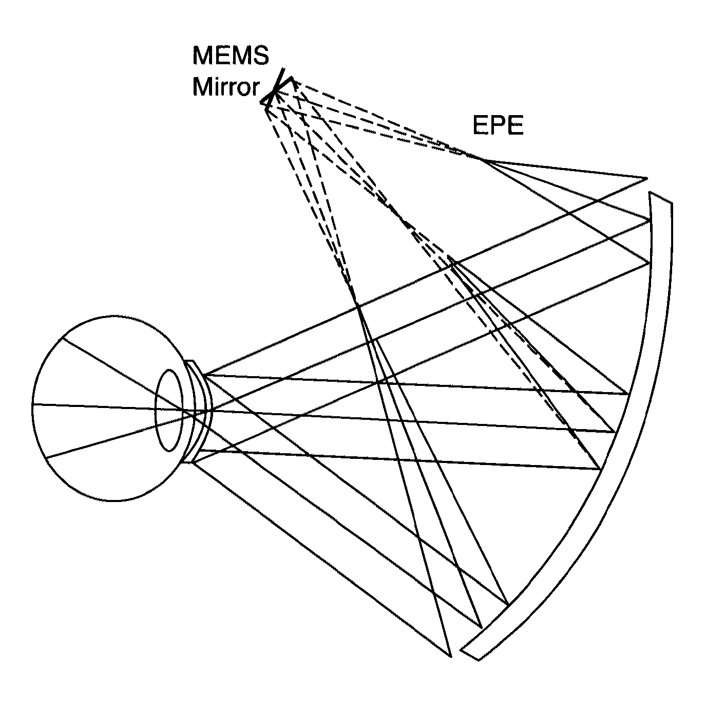
[0011]Due to the use of
retinal scanning display technology, the “pixels” of imagery are generated by
laser beams entering the eye from an array of angles. The
divergence of the laser beams as they enter the eye specifies the focus of the imagery. In a preferred embodiment a focus adjuster is incorporated to vary the
divergence of the scanning laser beams, thereby controlling the focus of the imagery.
[0012]The key innovations of present invention include curved primary mirrors in front of the eyes that are lightweight and provide a large display field of view, and in
augmented reality mode, a large unimpeded look-through field of view. Preferred embodiments utilize
narrowband rugate reflective coatings in
augmented reality mode to maximize transmission of light from the outside scenery, yet ensure that no significant amount of light can escape from the display. These preferred embodiments permit, for example, a soldier,
pilot or surgeon to view live environments in augmented reality mode with a substantially unimpeded field of view and unimpeded transmission. The present invention includes an eye tracker that is simple and robust. Preferred embodiments utilize existing retinal scanning display hardware. Preferred embodiments use direct
diode laser modulation and two-dimensional MEMS scanners to provide laser beams which are reflected from a
curved mirror into the eye of the wearer so as to provide high resolution only where it is needed, and
low resolution everywhere else. Preferred embodiments use a reverse “
wavefront coding” concept to correct residual aberrations resulting from the use of the
curved mirror. In one preferred embodiment, the
curved mirror in front of the eye is spherical and the display field of view is 70°. In another preferred embodiment the mirror in front of the eye is ellipsoidal allowing for an extremely large display field of view such as 120 degrees. The eye is in some sense a megapixel device as the
optic nerve contains approximately 1 million fibers. The MEMs-based
laser scanning engines proposed for the present invention each have 0.92 megapixel capability. Since one
scanner is utilized for foveal vision and one for
peripheral vision, the information capacity of the proposed head mounted display rivals what the eye is capable of receiving.

