Polymer-doped vertically-aligned nematic liquid crystals

a vertical alignment, liquid crystal technology, applied in the field of liquid crystals, can solve the problems of high contrast of van-lcds at the expense of the response time of the display, drawbacks of current ps-va technology, and difficult irradiation step

Active Publication Date: 2012-05-03
CALIFORNIA INST OF TECH +1
View PDF1 Cites 6 Cited by
  • Summary
  • Abstract
  • Description
  • Claims
  • Application Information

AI Technical Summary

Benefits of technology

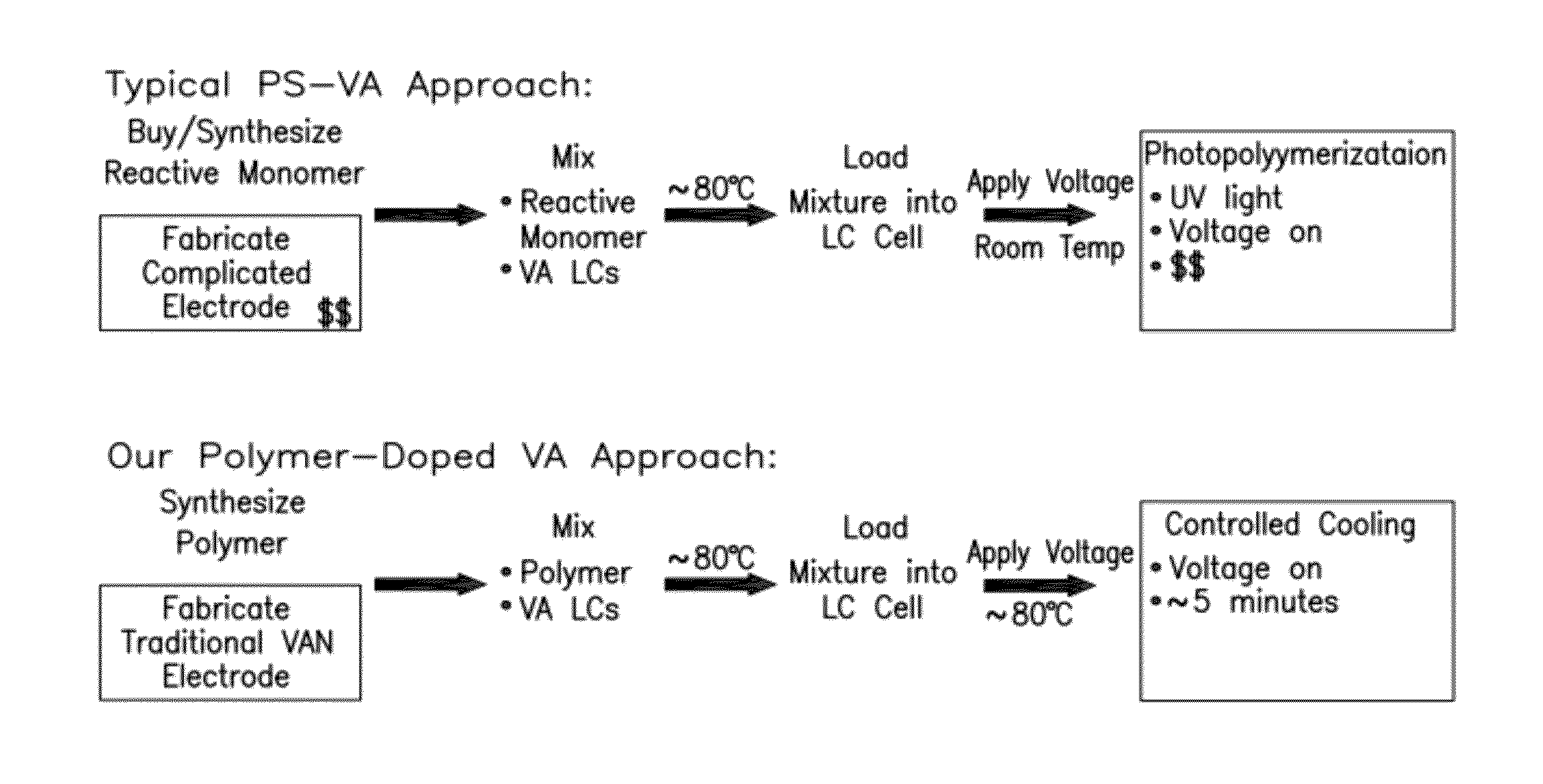
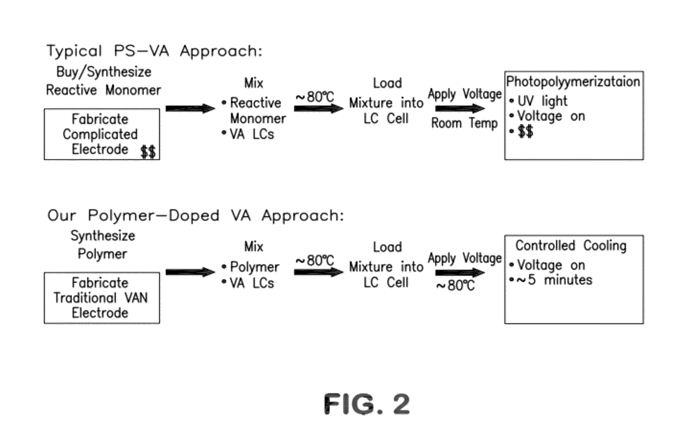
[0007]Provided is a technology that significantly improves both the processing and device characteristics of vertically aligned nematic liquid crystal systems. The system described here generally uses polymers synthesized and purified outside of the display that are added at low concentration to the nematic liquid crystal that makes up the active medium of the LCD. The material comprising a small concentration of polymer dissolved in a liquid crystal is referred to as a polymer-doped LC (PD-LC). It was found that the PD-LC system described here can increase contrast (eliminating or reducing the problem of light leakage that plagues PS-VA technology, for example) and improve switching speed without introducing ionic and radical impurities produced during UV irradiation. By using polymer dopants that dissolve uniformly in the active medium of the display, in an aspect the system described here maintains the optical uniformity of the LC and avoids the polymerization-induced phase-separation that occurs during photopolymerization of monomers in LCs. Very low concentrations of polymer dopant are sufficient to produce improvements in the physical properties of VAN systems.
[0008]In an aspect, polymer-doped LCs which maintain the excellent dark state and high contrast that are the hallmarks of vertically aligned nematic liquid crystal displays and that improve one or more liquid crystal display properties including increasing the switching speed, enhancing the brightness, and improving the viewing angle of vertically-aligned nematic liquid crystal displays (VAN-LCDs) are provided. In an aspect, the polymer dopants provided confer these benefits without detrimental effects on the cell's threshold voltage or saturation voltage. In an aspect, the compositions provided are fundamentally different than existing monomer-doped in situ polymerized LCs used in PS-VA technology because the compositions provided eliminate exposure of the liquid crystal to UV light and its concomitant radical contamination. Devices free of radical contamination have increased display lifetimes in addition to their advantageous switching speeds and optical properties.
[0012]In an aspect of the invention, the switching speed of a nematic liquid crystal composition described herein is as fast (within 5%) or faster than the switching speed of the VAN host without the liquid crystal polymer. In an embodiment, the optical rise time of a nematic liquid crystal composition described herein is approximately equal to (within 5%) or faster than the optical rise time of the VAN host without the liquid crystal polymer. In an embodiment, the optical fall time of a nematic liquid crystal composition described herein is approximately equal to (within 10%) or faster than the optical fall time of the VAN host without the liquid crystal polymer. In an aspect of the invention, the addition of the liquid crystal polymer to the VAN host improves the contrast of the mixture in a cell or device. In an aspect of the invention, response speed of devices containing the nematic liquid crystal compositions described herein is improved as compared to the response speed of devices which do not contain the liquid crystal polymer, as described herein. In an aspect of the invention, the nematic liquid crystal compositions described herein have one or more of the effects described herein. In an aspect of the invention, either or both of the rise time and fall time of devices containing the nematic liquid crystal compositions described herein is improved from 0% (i.e., no decrease in rise or fall time or both) up to more than one hundred percent, as compared to the rise and fall time of devices which do not contain the liquid crystal polymer, as described herein. In an embodiment, the rise time of devices containing the nematic liquid crystal compositions described herein is improved from 0% (i.e., no decrease in rise time) to an improvement of about 2X faster, as compared to the rise time of devices which do not contain the liquid crystal polymer, as described herein. In an embodiment, the fall time of devices containing the nematic liquid crystal compositions described herein is improved from 1% to about 50%, as compared to the fall time of devices which do not contain the liquid crystal polymer, as described herein.
[0055]Also provided is an optical device comprising two opposing electrode surfaces which have a nematic liquid crystal composition described herein disposed therebetween. In an embodiment, the optical device has improved contrast as compared to an optical device containing no crystal polymer. In an embodiment, the optical device has improved switching speed as compared to an optical device containing no liquid crystal polymer. In an embodiment, the optical device has improved viewing-angle symmetry as compared to an optical device containing no liquid crystal polymer.

Problems solved by technology

However, the very high contrast of VAN-LCDs comes at the expense of the response time of the display: a pixel in a current VAN display requires approximately 100 ms to switch (rise-time+fall-time), compared to less than 20 ms for a TN display.
Although polymer-stabilized vertical-alignment (PS-VA) technology improves the switching speed in HD LCD, there are drawbacks to current PS-VA technology.
Current PS-VA technology introduces a difficult irradiation step during processing to induce polymerization of the monomer, which requires precise control of the uniformity and the duration of UV irradiation.
Also, the radical and ionic species created during UV radiation have long-term deleterious effects on the LCD (such as increasing the power consumption and reducing the display lifetime).

Method used


Image

  • Polymer-doped vertically-aligned nematic liquid crystals
  • Polymer-doped vertically-aligned nematic liquid crystals
  • Polymer-doped vertically-aligned nematic liquid crystals

Examples


Embodiment Construction

[0077]Without wishing to be bound by any particular theory, there can be discussion herein of beliefs or understandings of underlying principles or mechanisms relating to the invention. It is recognized that regardless of the ultimate correctness of any explanation or hypothesis, an embodiment of the invention can nonetheless be operative, and useful.

[0078]In general, the terms and phrases used herein have their art-recognized meaning, which can be found by reference to standard texts, journal references and contexts known to those skilled in the art. The definitions are provided to clarify their specific use in the context of the invention.

[0079]As used throughout the present description, the expression “a group corresponding to” or a “group” an indicated species expressly includes a radical, including monovalent, divalent and polyvalent radicals for example, an aromatic or heterocyclic aromatic radical, of the groups listed provided in a covalently bonded configuration, optionally...


PUM

PropertyMeasurementUnit
threshold voltageaaaaaaaaaa
melting pointsaaaaaaaaaa

Abstract

A system having a vertically-aligned negative delta E nematic liquid crystal host material and a small amount of liquid crystal polymer is provided. The liquid crystal polymer improves the switching speed of a vertically aligned nematic system without sacrificing contrast or viewing angle.

Description

CROSS-REFERENCE TO RELATED APPLICATIONS[0001]This application claims priority to U.S. provisional application Ser. No. 61 / 369,574, filed Jul. 30, 2010 which is incorporated by reference in its entirety.STATEMENT REGARDING FEDERALLY SPONSORED RESEARCH OF DEVELOPMENT[0002]This invention was made with government support under IIP0946085 awarded by the National Science Foundation. The government has certain rights in the invention.BACKGROUND OF THE INVENTION[0003]The present invention relates generally to liquid crystals, and more particularly to nematic liquid crystals.[0004]The public's growing demand for the superior image quality provided by high definition televisions (HDTVs) has resulted in ongoing growth of HDTV sales. To compete in today's market, a display needs to meet three main criteria: high contrast, good viewing angle and fast response times. Vertically Aligned Nematic (VAN) Liquid Crystal Displays (LCDs) have inherently high contrast and, with some simple modifications, ...

Claims


Application Information

Patent Timeline
Patent Type & Authority Applications(United States)
IPC IPC(8): C09K19/02C09K19/46C09K19/44C09K19/42
CPCC09K19/3003C09K19/3842C09K19/406C09K2019/3004C09K2019/3009C09K2019/301C09K2019/3016C09K19/3847
Inventor KORNFIELD, JULIA A.WAND, MICHAELKURJI, ZULEIKHA
Owner CALIFORNIA INST OF TECH
Why Eureka
Try Eureka