
Method for applying optical filter structures onto a carrier substrate

a technology of optical filter structure and carrier substrate, which is applied in the direction of colour screen additive process, optical elements, instruments, etc., can solve the problems of unserviceable filter, slight distortion or tensile strain of film especially in the rolling direction, and impairment of the optical action of the filter structure, so as to achieve simple and reliable application of optical filter structure, less susceptible to faults, and easy handling

Active Publication Date: 2012-05-10
3D GLOBAL HLDG GMBH
View PDF5 Cites 2 Cited by
  • Summary
  • Abstract
  • Description
  • Claims
  • Application Information

AI Technical Summary

Benefits of technology

"The invention provides a simple and reliable method for applying optical filter structures onto a substrate, which is transparent to light. The method involves applying an adhesive to the substrate, then placing a photographic film with the adhesive in contact with it. The adhesive is spread by moving a roller across the film, resulting in a uniform thickness of the adhesive layer. The method is less susceptible to faults and easier to handle than previous methods. The invention also provides a contact pressure and feed rate that are matched to each other, resulting in optimal performance. The method can be used with various adhesives and curing methods. The joined system created by the method is permanent and can be used in various applications."

Problems solved by technology

The two laminating operations generally involve the risk that dust particles, fluff or other flaws such as, for example, air bubbles, get embedded into the photographic emulsion layer, which may lead to noticeable impairments of the optical action of the filter structure.
In the worst case, this makes the filter unserviceable.
Especially in case of large-area photographic films, the pressure of between 50 and 70 kPa that has to be applied for laminating, commonly by means of a roller or a cylinder, leads to a slight distortion or tensile strain of the film especially in the rolling direction.
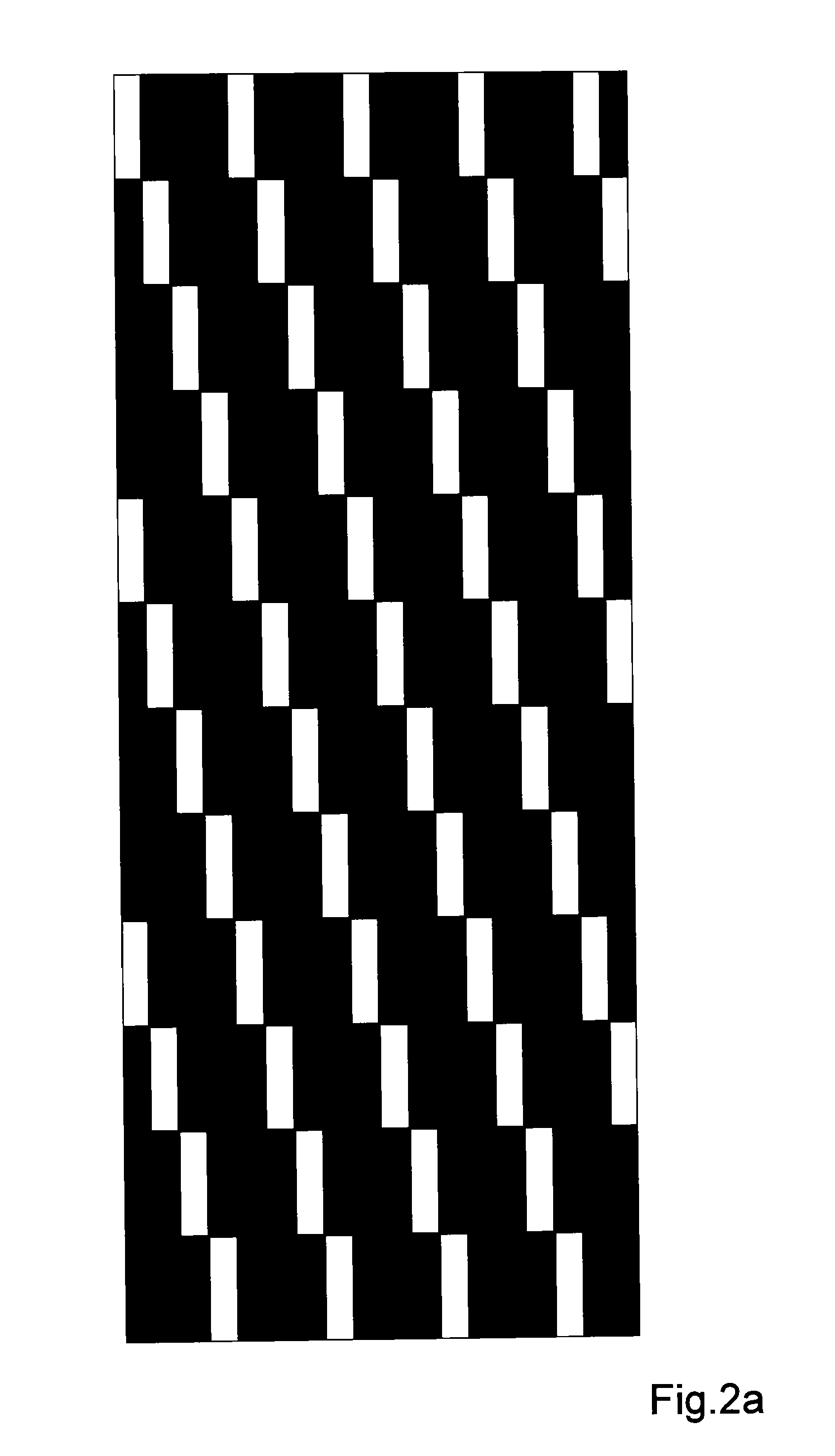
In the case of filter structures for screens for three-dimensional display, which feature a periodicity, this will impair the accuracy of periodicity, which may make such a filter unserviceable.
The method of fabrication described above causes problems also if several of these optical filter structures are applied onto the substrate simultaneously.
This can be done by means of suitable carbide-tipped glass cutters, but time and again this causes unforeseeable, irregular break edges and chips so that the entire, already manufactured optical filter has to be scrapped.
Sometimes, the system of layers as a whole prevents clean separation and also causes sharp-edged fractures that not only make the product unfit for further use but also involve a severe risk of injury.
It is known that operators, even though they wear gloves, frequently get their fingers cut.
Printing the optical filter structures onto the glass surface as an alternative fabricating method is unsuccessful, as the filter structures will not properly adhere to the optically smooth glass surface.
The screen printing process will not produce optical structures of the necessary smallness and accuracy either.

Method used


Image

  • Method for applying optical filter structures onto a carrier substrate
  • Method for applying optical filter structures onto a carrier substrate
  • Method for applying optical filter structures onto a carrier substrate

Examples


Embodiment Construction

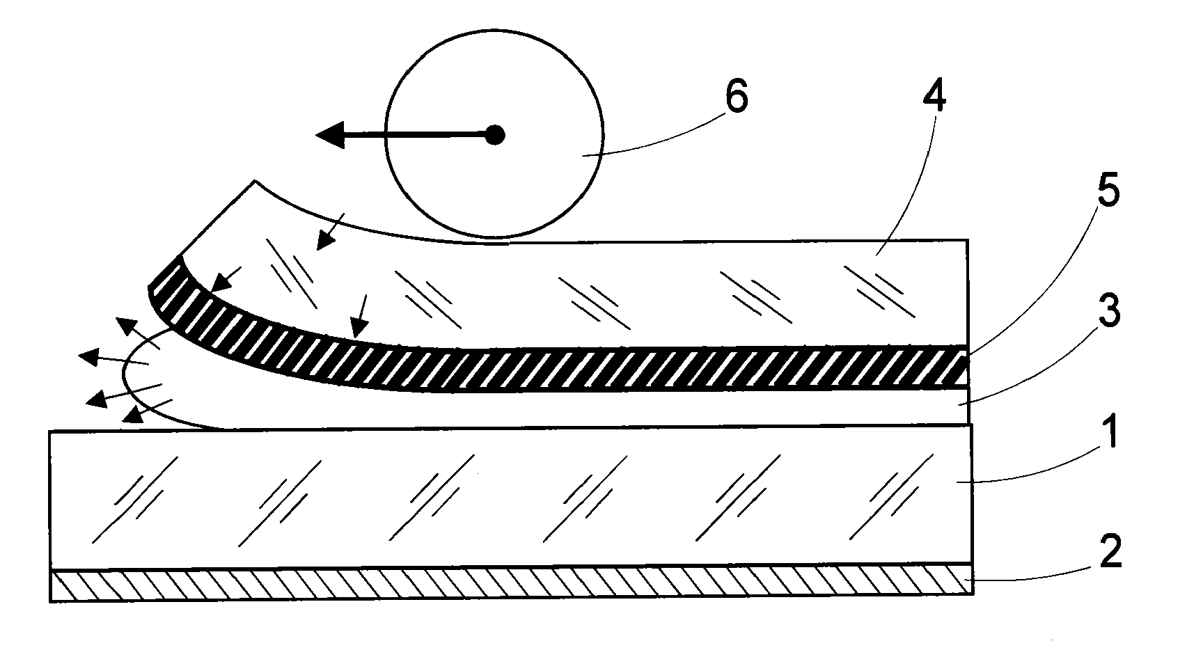
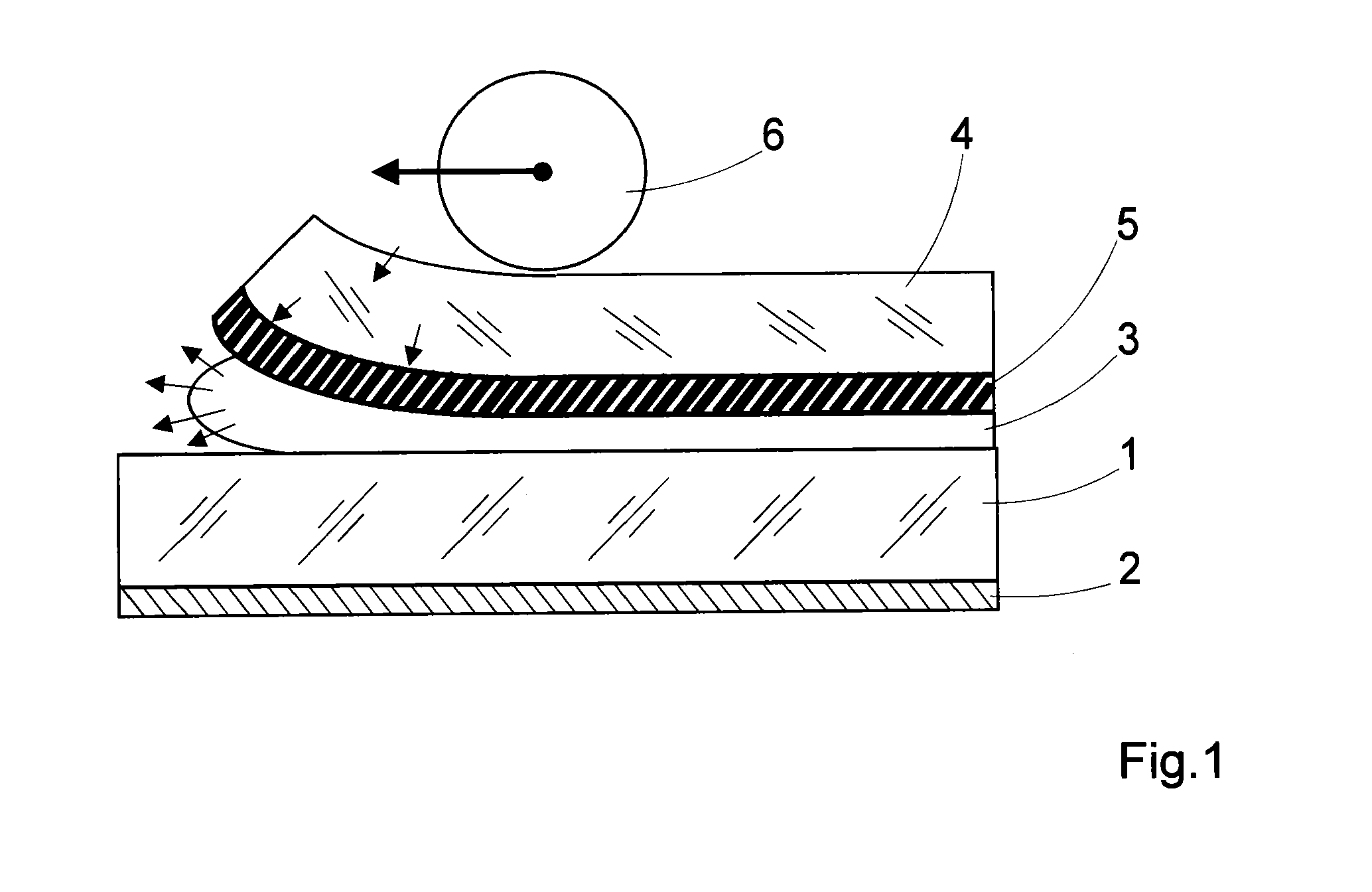
[0037]Described below are methods with which optical filter structures—for example, barrier filters for three-dimensional display—may be applied onto a substrate transparent to light at least in the visible wavelength range. FIG. 1 illustrates the essential elements that play a part in the process step explained further below. The substrate 1 may be glass, which, as a rule, has the form of a planar, rectangular solid. Here, the bottom side of substrate 1 is provided with an antireflection coating 2; this coating is, however, not absolutely necessary but is only provided for comfortable viewing. An adhesive 3 is applied onto the top side of substrate 1. The adhesive 3 may be a viscous adhesive consisting of monomers, which polymerize and cure under irradiation with ultraviolet light.

[0038]In the process step illustrated in FIG. 1, a photographic film comprising a base film 4 and a photographic emulsion layer 5 applied on the base film is brought into contact with the adhesive 3 so th...


PUM

PropertyMeasurementUnit
contact pressureaaaaaaaaaa
thicknessaaaaaaaaaa

Abstract

A method by which optical filter structures may be applied onto a substrate that is transparent to light at least in the visible wavelength range suitable for a barrier filter.In such a method, an adhesive is applied onto the substrate; then, a photographic film comprising a base film and a photographic emulsion layer applied on it is brought into contact with the adhesive. The optical filter structures are impressed in the photographic emulsion layer by exposure, development and fixation. The side of the film brought into contact with the adhesive is the one that bears the photographic emulsion layer. The adhesive is then spread between film and substrate by means of a roller rolling across the film at a specified contact pressure and a specified feed rate of the roller and thus pressing the film against the substrate. A permanent joint between substrate and photographic emulsion layer is then established by the curing of the adhesive. In a further step, the base film may be thermally separated and removed from the photographic emulsion layer.

Description

PRIORITY CLAIM[0001]The present application is a National Phase entry of PCT Application No. PCT / EP2010 / 055049, filed Apr. 16, 2010, which claims priority from German Application Number 102009019761.3, filed May 5, 2009, the disclosures of which are hereby incorporated by reference herein in their entirety.FIELD OF THE INVENTION[0002]The invention relates to a method by which optical filter structures are applied onto a substrate that is transparent to light at least in the visible wavelength range.BACKGROUND OF THE INVENTION[0003]Filters that have a complex structure normal to the optical axis play an important part in many fields of optics. For example, so-called barrier filters are used to enable the viewer of a display screen to have a three-dimensional vision without further aids, provided that the picture contents to be displayed on the screen have been processed accordingly. Such filter structures can consist, for example, of an array, normal to the optical axis, of areas tha...

Claims


Application Information

Patent Timeline
Patent Type & Authority Applications(United States)
IPC IPC(8): B32B38/10B29C65/02
CPCG03C7/12G02B5/201B29C65/14B29C65/48B29C70/086B29C70/34B29C70/504C08J5/12C09J5/00C09J5/06
Inventor DAEHNERT, ULLRICHSCHWARZ, JUERGENOTTE, STEPHAN
Owner 3D GLOBAL HLDG GMBH
Learn More