Method of allocating resource for relay

a wireless communication and resource allocation technology, applied in the direction of channel coding adaptation, frequency-division multiplex, broadcast service distribution, etc., can solve the problems of difficult to provide an efficient communication service in a wireless environment, the configuration of the wireless network is not so flexible, etc., to reduce the number of blind searches and efficiently conduct backhaul communication

Inactive Publication Date: 2012-05-10
LG ELECTRONICS INC
View PDF6 Cites 84 Cited by
  • Summary
  • Abstract
  • Description
  • Claims
  • Application Information

AI Technical Summary

Benefits of technology

[0015]According to an aspect of the present invention, a BS can efficiently conduct backhaul communication with one or more relays.
[0016]According to an aspect of the present invention, a relay can reduce the number of blind searches for a control channel to receive control information.
[0017]It will be appreciated by persons skilled in the art that that the effects that could be achieved with the present invention are not limited to what has been particularly described hereinabove and other advantages of the present invention will be more clearly understood from the following detailed description.

Problems solved by technology

However, wireless network configuration is not so flexible due to the fixed positions of BSs in the wireless communication system.
In addition, it is difficult to provide an efficient communication service in a wireless environment experiencing fluctuations in the number of required calls.

Method used


Image

  • Method of allocating resource for relay
  • Method of allocating resource for relay
  • Method of allocating resource for relay

Examples


embodiment 1

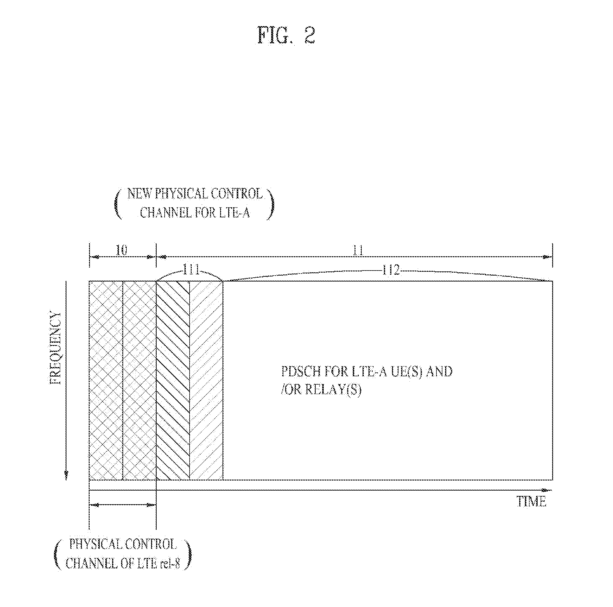
[0046]In accordance with embodiments of the present invention, a new PDCCH may be configured in a subframe to transmit control information to relays, with backward compatibility to LTE rel-8 according to the quality and traffic load of a wireless backhaul link. A physical control channel may be configured for relays at a predetermined position or at a variable position in a subframe.

[0047]FIG. 2 illustrates an exemplary frame structure according to an embodiment of the present invention.

[0048]According to the embodiment of the present invention, it is assumed that a BS allocates resources to each relay according to the traffic load of the relay in the same manner as it allocates resources to a UE and signals the allocated resources to the relay on a physical control channel. It is also assumed that a new physical control channel is added for relays, with backward compatibility to an LTE Release 8 system. The subframe structure illustrated in FIG. 2 is based on the premise that a phy...

embodiment 2

[0088]Now a description will be given of a semi-static resource allocation method according to another embodiment of the present invention, in which a BS predetermines resources for backhaul communication between the BS and a relay and signals the predefined resources to the relay.

[0089]In the embodiment of the present invention, the BS may predetermine a subframe pattern for backhaul communication, a specific frequency band in which a channel region is allocated to a relay in a subframe, a Modulation and Coding Scheme (MCS) level for the channel region, etc. during initial setup for each of a plurality of relays, taking into account the channel quality of a backhaul link, the cell size of the relay, and the traffic load of the relay. Even though a specific subframe pattern, a specific frequency band, and a specific MCS level have already been predefined for each relay, the BS may signal a modification to the relay by higher-layer signaling, when it is necessary to change at least o...


PUM


Abstract

A method for wireless backhaul communication between a base station and a relay is disclosed. The base station enables a physical control channel to be set up, separately from the terminal that is used to transmit control information to each relay and the physical downlink control channel that has been set up. The base station can transmit data to the relay based on this control information. In a special embodiment, physical downlink control channel transmissions can be minimized by prescribing in advance the transmission of control information between the base station and the relay.

Description

FIELD OF THE INVENTION [0001]The present invention relates to a method for allocating resources for wireless communication and more particularly, to a method for allocating a predetermined amount of channel resources to a relay at a Base Station (BS).BACKGROUND ART [0002]In a typical wireless communication system, since signals are transmitted and received between a fixed BS and a User Equipment (UE) via a direct link, a highly reliable radio link can be readily established between the BS and the UE. However, wireless network configuration is not so flexible due to the fixed positions of BSs in the wireless communication system. In addition, it is difficult to provide an efficient communication service in a wireless environment experiencing fluctuations in the number of required calls. To overcome these shortcomings, a multi-hop relay data transmission scheme can be implemented through fixed relays, mobile relays, or general UEs in the typical wireless communication system.[0003]FIG...

Claims


Application Information

Patent Timeline
Patent Type & Authority Applications(United States)
IPC IPC(8): H04B7/14H04W4/06H04W72/04
CPCH04L1/0003H04L1/0009H04L1/1861H04B7/14H04L5/0094H04L2001/0097H04B7/00H04L5/0053H04B7/15542H04L5/0032H04L5/0087H04J4/00H04W72/20
Inventor PARK, KYU JINCHUNG, JAE HOONCHO, HAN KYUKWON, YEONG HYEONMOON, SUNG HO
Owner LG ELECTRONICS INC
Why Eureka
Try Eureka