Radiation tube and radiation imaging system

a radiation imaging and tube technology, applied in imaging devices, instruments, nuclear engineering, etc., can solve the problems of reducing the service life increasing the cost and size of the x-ray tube, and deteriorating the performance of the grating, so as to improve the image quality of the phase contrast image, the distance between the focal point of the radiation and the multi-slit is shortened, and the cost and size of the radiation tube are not increased.

Inactive Publication Date: 2012-05-31
FUJIFILM CORP
View PDF0 Cites 7 Cited by
  • Summary
  • Abstract
  • Description
  • Claims
  • Application Information

AI Technical Summary

Benefits of technology

[0011]An object of the present invention is to provide a radiation tube capable of arranging a multi-slit in a position closest to an X-ray focal point without affecting the cost and the size of the radiation tube, and a radiation imaging system using a radiation tube.
[0017]According to the present invention, the multi-slit is provided to the radiating portion. Accordingly, a distance between the focal point of the radiation and the multi-slit is shortened compared with a conventional imaging system in which the multi-slit is arranged outside of the radiation source. Thereby, a noncoherent component and a scatter component of the radiation are reduced. As a result, the image quality of the phase contrast image is improved. Because the multi-slit is not enclosed in the vacuum envelope, the cost and the size of the radiation tube do not increase from those of the conventional radiation tube. Moreover, because the multi-slit is in contact with the housing or the vacuum envelope, the multi-slit is excellent in heat dissipation. As a result, the multi-slit of the present invention is less affected by heat.
[0018]A multi-slit pattern is provided to the X-ray transmitting member of the radiation window just by making a change to a conventional radiation tube and it is relatively easy. The distance between the focal point of the radiation and the multi-slit pattern is further shortened when the multi-slit is provided to the vacuum envelope. According to the radiation imaging system of the present invention, the image quality of the phase contrast image is improved with the use of the radiation tube of the present invention.

Problems solved by technology

Accordingly, cost and size of the X-ray tube increase.
Thus, the temperature rise results in deterioration of grating performance and poor durability.

Method used


Image

  • Radiation tube and radiation imaging system
  • Radiation tube and radiation imaging system
  • Radiation tube and radiation imaging system

Examples


first embodiment

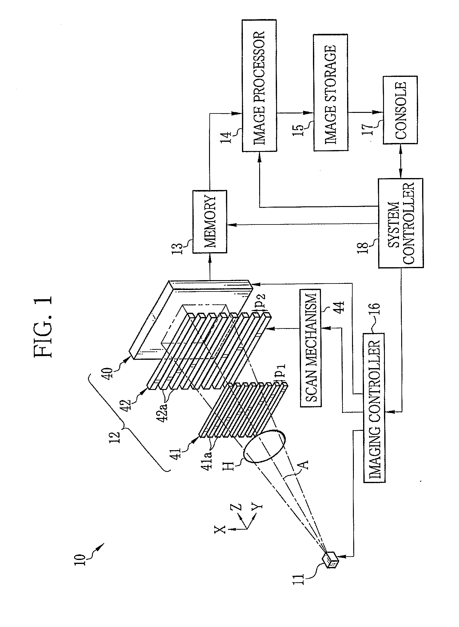
[0026]As shown in FIG. 1, a radiation imaging system, for example, an X-ray imaging system 10 of the present invention is provided with an X-ray source 11 and an imaging unit 12. The X-ray source 11 applies X-rays to an object H. The imaging unit 12 is arranged to face the X-ray source 11. The imaging unit 12 detects the X-rays, applied from the X-ray source 11 and then passed through the object H, to generate image data. The imaging unit 12 is connected to a memory 13. The memory 13 stores the image data read out from the imaging unit 12. The memory 13 is connected to an image processor 14. The image processor 14 processes multiple image data stored in the memory 13 to generate a phase contrast image, and then stores the phase contrast image in image storage 15. The X-ray source 11 and the imaging unit 12 are controlled by an imaging controller 16. A system controller 18 controls overall operation of the X-ray imaging system 10 based on an operation signal inputted from a console 1...

second embodiment

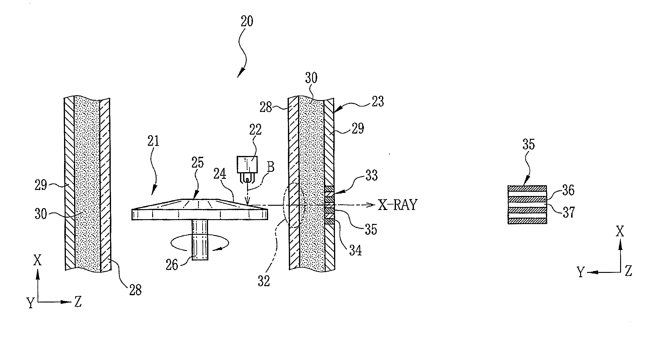
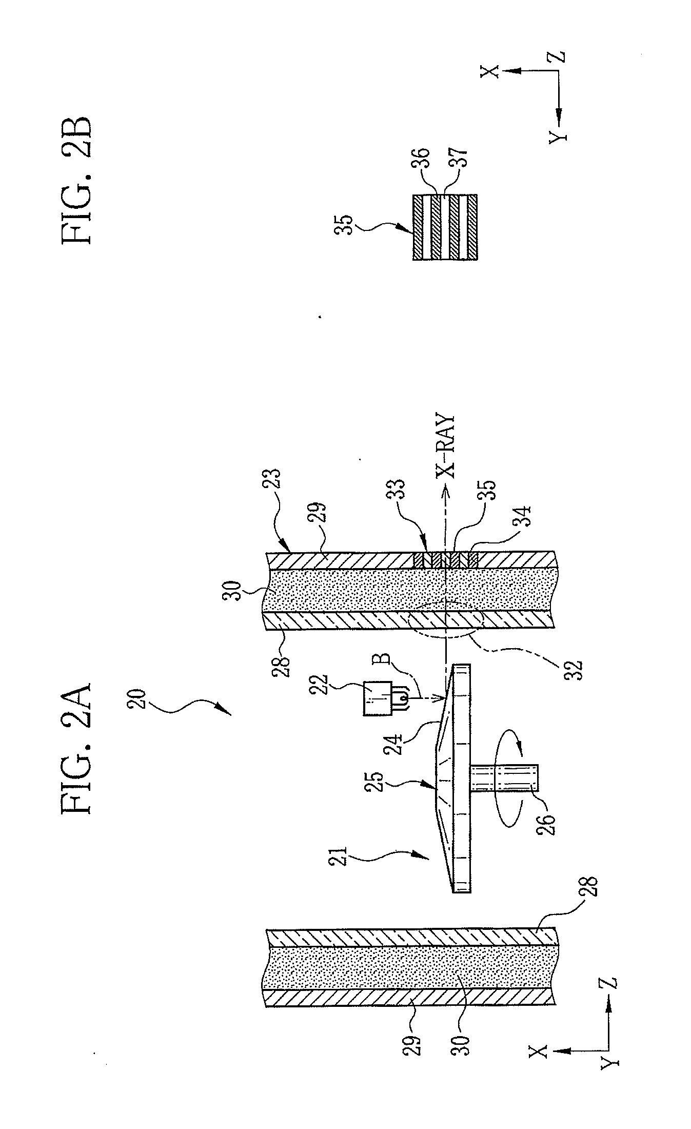
[0050]Like an X-ray tube 50 shown in FIG. 4, a radiation window 51 of the housing 29 may be composed of the opening 34 and an X-ray transmitting member 52 filled or fixed inside the opening 34, in a manner similar to the conventional X-ray tube. A multi-slit pattern 53 may be formed on one of inner and outer surfaces of the X-ray transmitting member 52. The multi-slit pattern 53 is made from a material with high X-ray absorption property, for example, gold, platinum, silver, lead, or tungsten. According to this configuration, a change or improvement is made to the conventional X-ray tube to achieve the effects similar to or the same as those of the X-ray tube 20 in the first embodiment.

third embodiment

[0051]Like an X-ray tube 60 shown in FIG. 5, a radiation window 61 of the housing 29 may be composed of the opening 34 and the X-ray transmitting member 52. A multi-slit pattern 62 may be formed on an inner surface of the X-ray passing portion 32 of the vacuum envelope 28. The multi-slit pattern 62 is made from a material with high X-ray absorption property, for example, gold, platinum, silver, lead, or tungsten. Thereby, the distance between the X-ray focal point and the multi-slit pattern 62 is more reduced than those in the first and second embodiments. When the X-rays pass through the insulating oil 30, x-ray scattering is likely to occur. In this embodiment, the X-ray source is made into a plurality of the linear light sources before the X-rays pass through the insulating oil 30. As a result, scatter components of the X-rays are reduced. Alternatively, the multi-slit pattern 62 may be provided to an outer surface of the X-ray passing portion 32 of the vacuum envelope 28.

[0052]I...


PUM

PropertyMeasurementUnit
sizeaaaaaaaaaa
peak wavelengthaaaaaaaaaa
phase contrast imageaaaaaaaaaa

Abstract

An X-ray tube has a cathode, a rotating anode, and a case for enclosing the cathode and the rotating anode. The rotating anode generates X-rays due to emission of electron beams from the cathode. The case includes a vacuum envelope for enclosing the cathode and the rotating anode, and a housing for enclosing the vacuum envelope. Inside of the vacuum envelope is maintained vacuum. The vacuum envelope has an X-ray passing portion for passing the X-rays therethrough. The housing is provided with a radiation window for radiating the X-rays, passed through the X-ray passing portion, to the outside of the case. The radiation window includes an opening and a multi-slit arranged in the opening. The multi-slit partly shields the X-rays, generated by the rotating anode, to form a plurality of virtual linear light sources.

Description

BACKGROUND OF THE INVENTION[0001]1. Field of the invention[0002]The present invention relates to a radiation tube for use in phase contrast imaging and a radiation imaging system using a radiation tube.[0003]2. Description Related to the Prior Art[0004]When incident on an object, radiation (for example, X-rays) changes its intensity and phase due to interaction with the object. It is known that the phase change interacts more strongly than the intensity change with the object. X-ray phase imaging takes advantage of this property. Using the X-ray phase imaging technique, a high contrast image (hereinafter referred to as the phase contrast image) of an object with low X-ray absorption is captured based on the phase change (angular change) of the X-rays caused by the object. Researches on the X-ray phase imaging have been conducted actively.[0005]An X-ray imaging system using a Talbot-Lau interferometer is known as an X-ray phase imaging apparatus (see, U.S. Patent Application Publicat...

Claims


Application Information

Patent Timeline
Patent Type & Authority Applications(United States)
IPC IPC(8): G01N23/02H01J35/06
CPCG21K1/06H01J2235/18H01J35/16G21K2207/005
Inventor KANEKO, YASUHISA
Owner FUJIFILM CORP
Why Eureka
Try Eureka