[0020]The preferred embodiment of a regenerative
braking system 10 for an
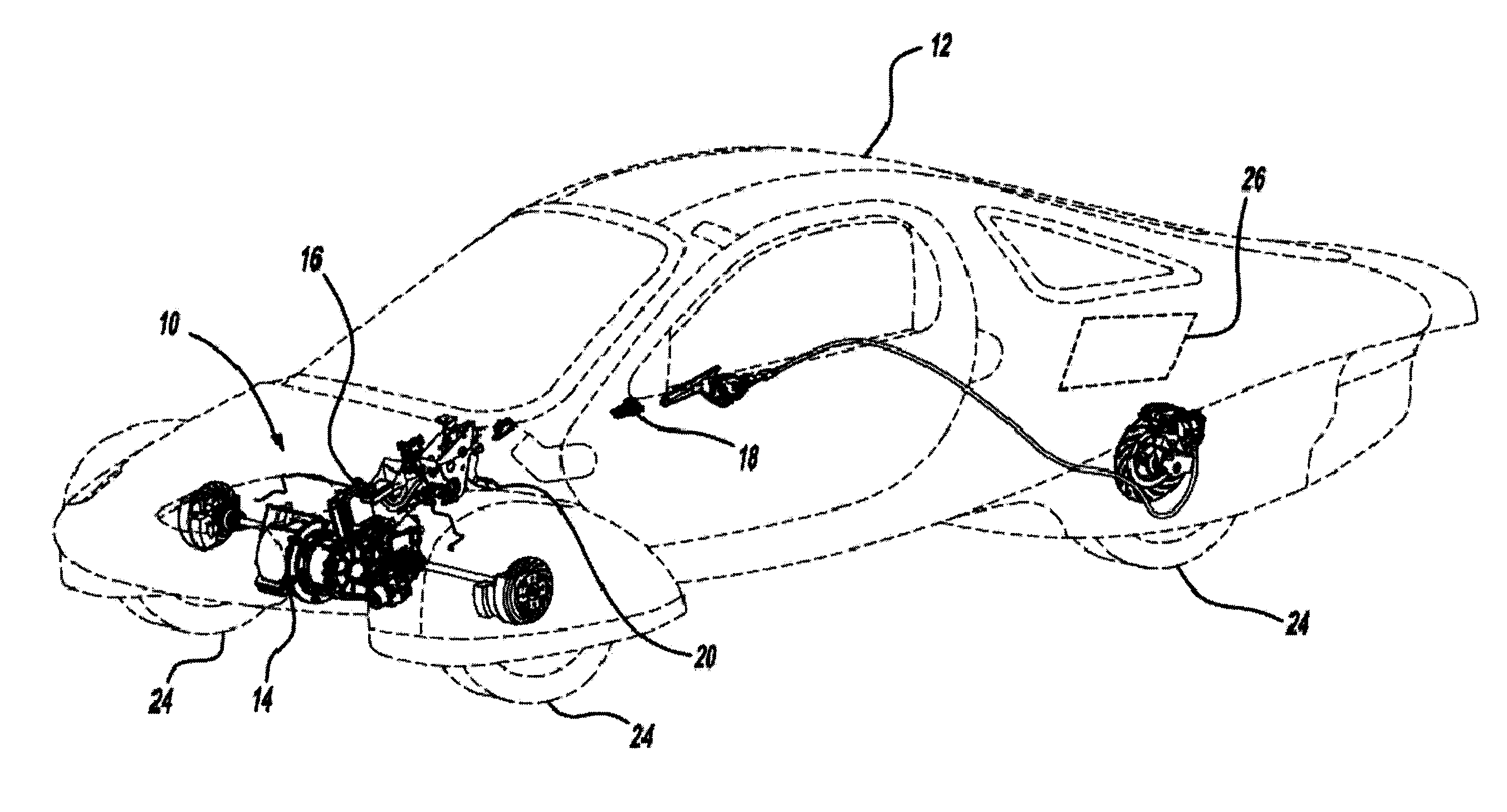
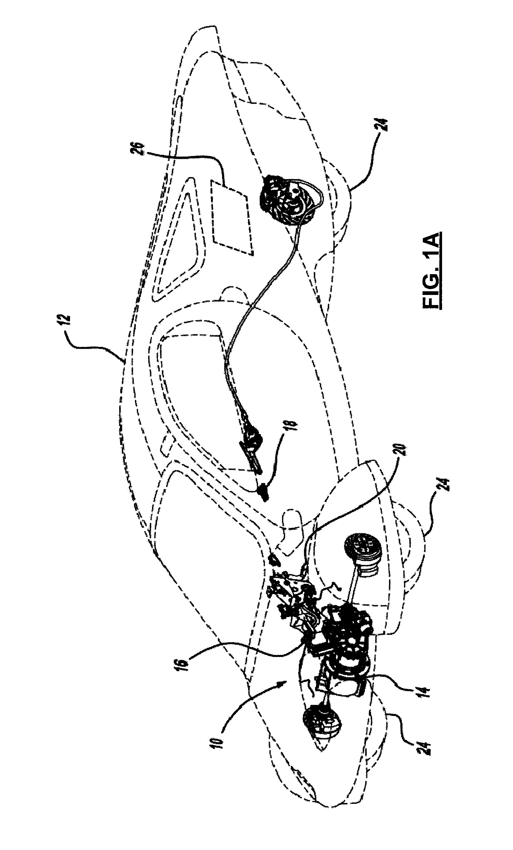
electric drive vehicle 12 is illustrated and described with respect to FIGS. 1 through 12.
System 10, as described herein, allows kinetic energy from vehicle 12 to be re-absorbed by an
energy storage system, achieves a consistent
braking system meeting Federal Motor
Vehicle Safety Standards (FMVSS), and meets specific performance objectives (e.g., stopping distance, pedal force application, relationships between brake pedal force, displacement, and vehicle deceleration, etc.), while smoothly blending the transition between electrical regenerative braking and friction braking.
[0028]Adjustable knob 28 includes a plurality of
detent mechanisms (not shown) corresponding to discrete levels of regenerative braking from accelerator pedal 22 or any other sensor separate from brake pedal 20. For example, adjustable knob 28 may include 16
detent locations for adjusting the intensity, while still obtaining the maximum amount of energy possible from regenerative braking system 10. Adjustable knob 28 may be tuned to provide the vehicle occupant with the intended driving experience and to meet vehicle targets. As should be understood, adjustable knob 28 may be tuned to provide any value between 0% to 100% of the
potential electrical braking. In this way, the vehicle operator may adjust vehicle 12 to provide an appropriate balance between comfort and vehicle efficiency. It should be understood that with a higher level of electrical braking, vehicle 12 becomes more energy-efficient. User-adjustable regenerative braking is at accelerator pedal 22, but boost from brake pedal 20 operates under a fixed
algorithm (i.e., not adjustable by the vehicle operator). Notably, however, these values are interconnected, as will be described in detail below.
[0029]Electronic shift controller 18 is a low-speed (e.g., operating at 100 kbps) controller
area network-based system (CAN) requiring only four circuits (e.g., battery feed circuit, ground, and two CAN functions). Accordingly, less wiring, weight, and cost are required for operation. Furthermore, the CAN-based system provides the ability to override current shift mode into park mode if vehicle 12 is in drive mode after the vehicle occupant exits vehicle 12. Electronic shift controller 18 also includes built-in diagnostic settings, which are utilized to prevent unintentional operation due to an inadvertent actuation of electronic shift controller 18. While the CAN-based system is described as operating at low speeds and having only four circuits, other speeds and numbers of circuits are contemplated. Furthermore, network-based CAN communication should be understood to be any
communication interface.
[0033]Communication between electronic shift controller 18 and ICM 66 allows for
visual feedback regarding regeneration level to the vehicle occupant through the vehicle's cluster display. Electronic shift controller 18, however, may provide feedback to the vehicle occupant in various other ways. For example, vehicle 12 may provide
audio feedback (e.g., an increased radio volume or tone, a voice indicator stating current regeneration level) and / or haptic feedback (e.g., varied resistance to rotation of adjustable knob 28, varied
detent length). With either
audio feedback or haptic feedback, the vehicle occupant would be alerted to regeneration level without having to view the vehicle's cluster display.
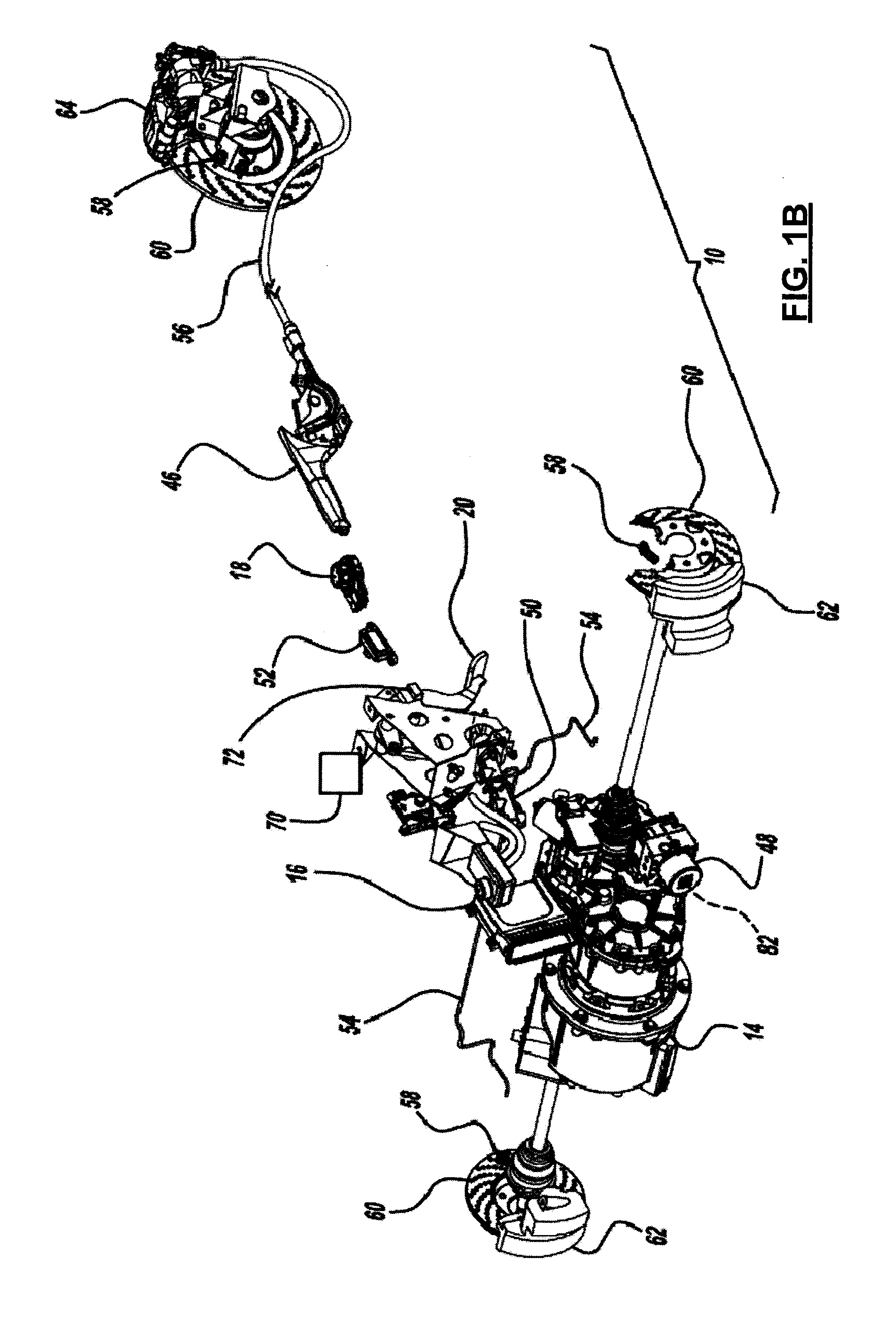
[0034]During braking, a brake pedal
position sensor 70 or stop
light switch 72 operably relays a
signal indicative of displacement of brake pedal 20 to VCU 16. VCU 16 may request an initial amount of regenerative braking based on this signal (i.e., “jump-in” regenerative braking). Additionally, the displacement of brake pedal 20 corresponds to a force applied to brake pedal 20 and an internal brake system
hydraulic pressure. VCU 16 may use this
hydraulic pressure, along with other inputs (e.g., vehicle speed via wheel speed sensors 58), to develop a
powertrain regenerative braking request from brake pedal 20. The request derived from brake pedal inputs is obtained from a fixed set of logic that is not adjustable by the vehicle operator. VCU 16 may receive the
hydraulic pressure and other inputs via the CAN. For example, pressure and vehicle speed may be fed through HECU 48, which then broadcasts the information on the CAN. By having
powertrain brake regeneration from brake pedal 20 via a fixed set of logic that is not user-adjustable, a vacuum boosted brake system may be eliminated while still meeting certain brake-related requirements under FMVSS. On a typical
electric vehicle without a source of vacuum from the engine, an electric
vacuum pump may be required for boost.
Powertrain brake regeneration from the brake pedal thus eliminates this need. Accordingly,
regenerative brake system 10 can be used as a brake boost for providing optimized brake system feel and performance without the need for a vacuum booster or other boosting means.
[0037]Regenerative braking system 10 may be initiated through various means. For example, regenerative braking system 10 may be initiated by stop
light switch 72 connected to brake pedal 20. As the vehicle operator displaces brake pedal 20, brake pedal
position sensor 70 sends a signal to VCU 16 indicative of brake pedal displacement. Pedal force is inferred from a brake
system pressure sensor (not shown) that may be located in HECU 48.
Brake pedal displacement activates stop
light switch 72, which is an input to a decision /
logic module 102 described in more detail below. In one configuration, this input can be used to initiate the “jump-in” regenerative braking while brake pads (not shown) on brake
calipers 62, 64 are being brought into contact with rotors 60 through the hydraulic system before significant brake line pressure is developed. This allows for a targeted pedal feel and a minimized amount of brake drag from pad-to-rotor contact when brake pedal 20 is not depressed.

