
Reactor

a reactor and mold resin technology, applied in the field of reactors, can solve the problems of deterioration of the insulation properties of enamel coatings, increased temperature in the interior of the reactor, and loss that the reactor body generates, so as to reduce the charge variation of mold resin, shorten the manufacturing time, and reduce the effect of cos

Active Publication Date: 2012-06-07
MITSUBISHI ELECTRIC CORP
View PDF6 Cites 44 Cited by
  • Summary
  • Abstract
  • Description
  • Claims
  • Application Information

AI Technical Summary

Benefits of technology

[0018]The present invention was made to solve the above-discussed problems and has an object of providing a small-sized reactor for use in a power converter for an electric power train for automobiles, the reactor enabling reduced charge variation of mold resin, a shorter manufacturing time and low cost, as well as improved heat radiation and a longer service life.
[0020]According to the reactor of the invention, due to such a construction that the inner bottom face of the case acting to house an induction component body has a plurality of surfaces having not less than two different heights, and the lower end face of the core is in contact with any of the above-mentioned surfaces of the inner bottom excluding the lowest inner bottom surface, even in the case that a mold resin, in which a filler material is mixed to improve heat conduction and of which viscosity is increased, is charged in a reactor of small sizes and of a high power density, coming round performance of the mold resin is improved, and positioning of the induction component on the occasion of housing it in the case and the insulation between the coil and case are made reliable, thus enable to reduce variation in resin charging.
[0021]Moreover, a shorter manufacturing time and lower manufacturing cost can be achieved, additionally heat radiation is improved to suppress an operation temperature difference at the time of operation and non-operation of the reactor, and the degree of expansion or contraction is decreased thus enabling to prevent cracks from being generated in the mold resin resulting in defective insulation, as well as it can be prevented that the joule loss of a coil is increased resulting in reduced efficiency.
[0022]Consequently, it becomes possible to obtain a reactor suitable for use in a power converter for a power train of electric vehicles such as hybrid cars or electric cars required to have high fuel consumption.

Problems solved by technology

In the case, however, of higher power density, despite its small sizes, the loss that the reactor body generates is not reduced and the temperature rise in the interior of the reactor tends to be larger.
In case of occurrence of high temperature of the coil, a molecular chain of polymeric materials that is applied onto the surface of the copper wire is decomposed and thus insulation properties of an enamel coating comes to be deteriorated, leading to the short circuit in a current path between turns of a conductive wire wound part of a coil, and characteristics of an expected inductance cannot be maintained but reduced.
In addition, a problem exits in that insulation properties having to be present between a peripheral member and a coil is lost, causing such difficulties as increase of leak current and dielectric breakdown, and eventually it becomes hard to obtain a desired service life.
That is, core and case have to be electrically insulated from the coil of the reactor, and the inability to maintain such insulation properties means a fault of the reactor.
Moreover, in addition to the above-mentioned electric insulation to be ensured, a problem exists in that the electric resistance of the wire conductor is increased based on the temperature coefficient of copper at high temperatures, and a joule loss at the coil portion is increased resulting in reduction of efficiency of the reactor.
In the above-mentioned conventional reactor, however, since the core or the coil of the reactor body is located in high density in the case, a problem exits in that a mold resin is not charged stably, and defective insulation or variation (unevenness) in heat radiation of each individual product is likely to occur.
Furthermore, another problem exists in a longer time needed to charge the mold resin and thus higher manufacturing cost.
That is, when a filler material is mixed in the mold resin, it is certain that heat conduction is improved, but the viscosity of the mold resin is increased to be hard to spread into a reactor body.
Accordingly, in a reactor constructed in small sizes, although the distance between the wire wound part of the coil that acts mainly as a heat-generated point and the case is desired to be shorter, there arises a further problem that the mold resin is not sufficiently spread to this part depending on the viscosity, and insulation properties in accordance with a desired service life cannot be obtained.
In addition, on the occasion of housing a reactor body in the case, in case of no reliable positioning, since the distance between the wire wound part of the coil and the case varies for each individual product, it comes to be difficult to cause a mold resin to spread with sufficient stability to suppress variation in insulation and variation in heat radiation.
Owing to charge variation, in case that air bubbles come in the mold resin or the mold resin cannot spread into the space in which the mold resin has to be spread, insulation cannot be obtained at this portion eventually resulting in defective insulation.
Furthermore, owing to expansion or contraction due to repeated high temperatures or low temperatures at the time of operation or non-operation of the reactor, there occurs such a failure that a contact state at the boundary between the mod resin and members such as core, case and coil comes to be unintended thus not to obtain a predetermined heat radiation.
However, there arises a still further problem that the resin charging work should be made at plural times and the air pressure of the work area should be changed between low-pressure environments and atmospheric pressure environments thus requiring a longer time eventually resulting in higher manufacturing cost.

Method used


Image

  • Reactor
  • Reactor
  • Reactor

Examples


embodiment 1

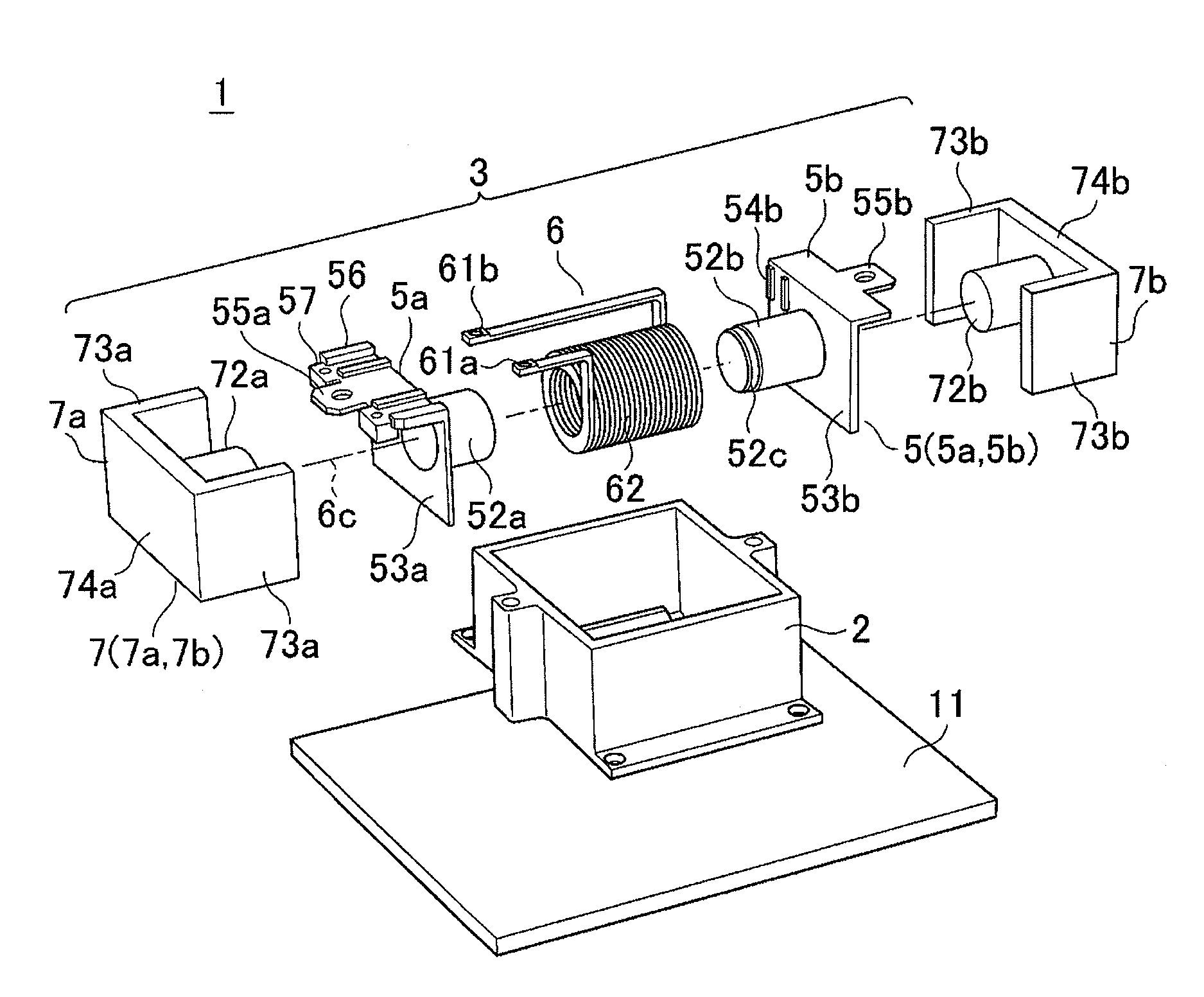
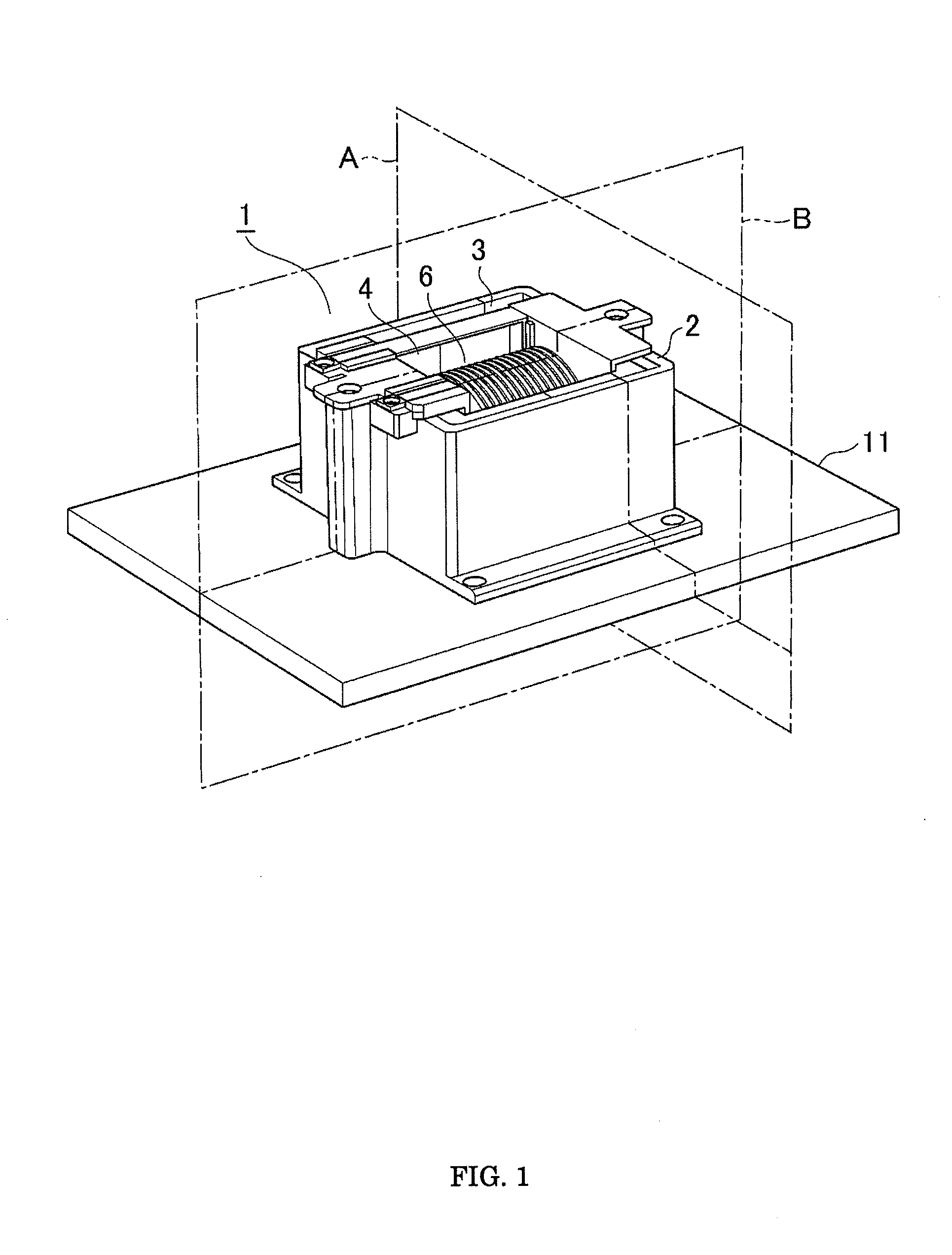
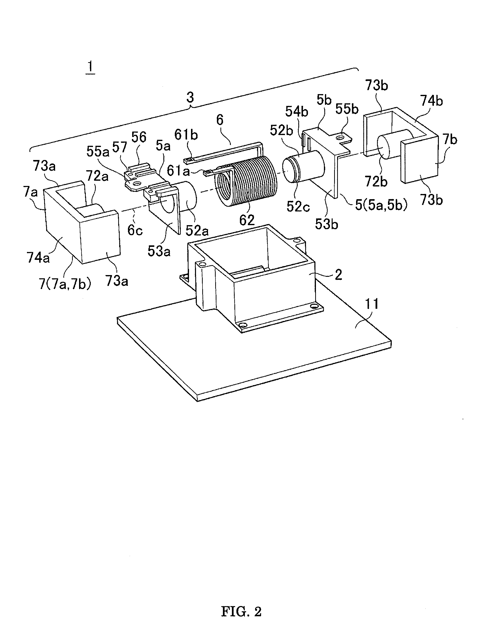
[0036]FIG. 1 is a perspective view illustrating a reactor according to a first embodiment of the invention, and FIG. 2 is an exploded perspective view illustrating exploded components of this reactor. Incidentally, the same reference numerals indicate the same or like parts throughout the drawings.

[0037]As is illustrated, a reactor 1 includes a case 2, an induction component 3 housed in this case 2 and a mold resin immersing the induction component 3 in the case 2. Furthermore, the induction component 3 is an assembly of separated insulation bobbins 5a and 5b, a coil 6 and separated core members 7a and 7b. Incidentally, the core members 7a and 7b are hereinafter simply referred to as a core.

[0038]In addition, between the underside of a wound circumference of a wire wound part 62 of the coil 6 and the inner bottom of the case 2, an insulating member 8 of a thin plate is interposed. The illustration of the insulating member 8, however, is omitted in FIG. 2.

[0039]The insulation bobbins...

embodiment 2

[0123]FIG. 8 is a perspective view illustrating an assembled state of a core 9a and a core 9b of the induction component 3 of the reactor 1 according to a second embodiment. FIG. 9, in the same manner as in FIG. 5, shows a projection view explaining the positional relationship between the interior of the case 2 and the core 9a, 9b taken from above the open face of the case 2.

[0124]In the second embodiment, the induction component 3 includes the core 9a, 9b instead of the core 7a, 7b in the first embodiment. The columnar part 72a, the outer leg part 73a and the side end part 74a of the core 7a in the first embodiment correspond to a columnar part 92a, an outer leg part 93a and a side end part 94a of the core 9a. Further, the columnar part 72b, the outer leg part 73b and the side end part 74b of the core 7b correspond to a columnar part 92b, an outer leg part 93b and a side end part 94b of the core 9b.

[0125]Moreover, the upper end face 7SU and lower end face 7SL of the outer leg part...

embodiment 3

[0146]With reference to FIG. 11, a third embodiment that is a modification of the reactor 1 according to the second embodiment is hereinafter described. FIG. 11 is a perspective view illustrating an assembled state of cores 90a and 90b of the induction component 3 of the reactor 1 according to the third embodiment of the invention.

[0147]In this third embodiment, the induction component 3 includes cores 90a, 90b instead of the cores 9a, 9b in the second embodiment. The columnar part 92a, the outer leg part 93a and the side end part 94a of the core 9a in the second embodiment correspond to a columnar part 902a, an outer leg part 903a and a side end part 904a of the core 90a, and the columnar part 92b, the outer leg part 93b and the side end part 94b of the core 9b in the second embodiment correspond to a columnar part 902b, an outer leg part 903b and a side end part 904b of the core 90b.

[0148]Furthermore, the outer leg part 93a of the core 9a, side end part 94a, outer leg part 93b of...


PUM


Abstract

The invention provides a reactor to be built in a power converter. In the reactor, an induction component composed of a coil being a winding of a conductor wire, a core in which interior a magnetic path is formed and an insulation bobbin positioning and engaging a wire wound part of the coil is housed in a case to be soaked with a mold resin. Inner bottom face of the case has a plurality of surfaces having not less than two different heights letting the outside bottom of the case a reference surface, and the lower end face of the core is in contact with any of the case inner bottom surfaces excluding the lowest inner bottom surface. As a result, the reactor is suitable for on-vehicle applications to achieve reduced article variation as well as a longer service life, a shorter operation time and decreased cost.

Description

FIELD OF THE INVENTION[0001]The present invention relates to a reactor for use in a power converter and, in particular, to a reactor suitable for on-vehicle applications that achieves reduced variation in performance, shorter operation time and decreased cost, by easy positioning and improving coming round performance of injection of a mold resin.DESCRIPTION OF THE RELATED ART[0002]Conventionally, a reactor has been used as a part of a power converter and is for use in, for example, a circuit part of a DC / DC voltage converter as an energy charge / discharge element. At the operation of a power converter, heat is generated when a coil of the reactor is energized. To allow this heat to transfer to the outside, an arrangement is employed such that heat is transferred to a sealing mold resin formed with respect to a case housing a reactor, and the heat is further radiated to the outside via a radiator plate.[0003]As an example of this reactor for use in a power converter to be mounted on ...

Claims


Application Information

Patent Timeline
IPC IPC(8): H01F27/02
CPCH01F27/022H01F37/00H01F27/306
Inventor KOBAYASHI, MASARUMITSUI, TAKAOIKEDA, MATAHIKOMORITAKE, NAOKIMAEKAWA, HIROTOSHIISHII, RYUICHIMATSUDA, KENJIYAMANE, TOSHINORI
Owner MITSUBISHI ELECTRIC CORP
Learn More