For users of light, the cost of lighting has two components, the first (purchase and installation) costs, and the cost of the
electricity (
operating cost).
While incandescent and fluorescent lamps have a relatively high
purchase cost efficacy, their luminous efficacy and operating costs are relatively high because of their low luminous efficacy.
However, conventional LED lamps are very expensive (about $80 to about $130 per lamp) and thus, even though the
electricity costs are typically about ¼ to about ½ that of incandescent lamps, the high first cost (also known as the
purchase cost) is sufficient to prevent widespread adoption.
Two key problems with prior art LED lamps are (1) the luminous efficacy of the
LED lamp is only about 50-70% of that achievable with an individual LED and (2) the very high first cost.
Although higher first costs can be mitigated by reduced operating costs and longer lifetimes, customers' price expectations often
pose psychological barriers to sales.
The cost element with the biggest
impact on the payback time is the first cost—for conventional LED lamps it is a virtually insurmountable obstacle.
The amortization payback time approach amortizes the lamp cost over its entire lifetime, thus resulting in shorter payback times than the out-of-pocket approach.
The lower luminous efficacy of prior art LED lamps compared to individual LEDs is caused by a number of factors including the reduction of luminous efficacy of the individual LEDs under actual operating conditions, the cost of assembling multiple LEDs into a lamp, the optical losses associated with the use of multiple LEDs in the lamp and fixture, the efficiency losses associated with the power converter and
LED driver and the further reduction in efficiency and lifetime of all components from high operation temperatures, which in turn is a result of high junction temperatures and
high current densities at which LED die are operated to achieve the desired total lumen output Each of these factors will be discussed in detail below.
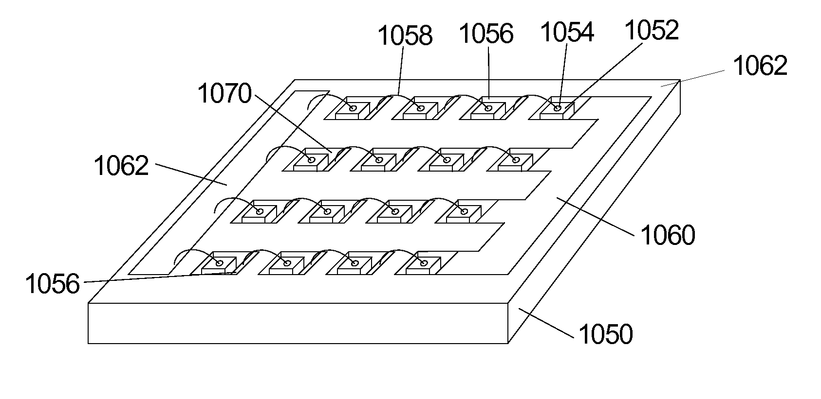
Very few individual LEDs produce enough light to be used individually for general lighting.
It is understood that a large number of individually packaged LEDs increases the lamp cost as it then includes the
package cost for each LED as well as the
assembly cost of putting all of the LEDs together in the lamp.
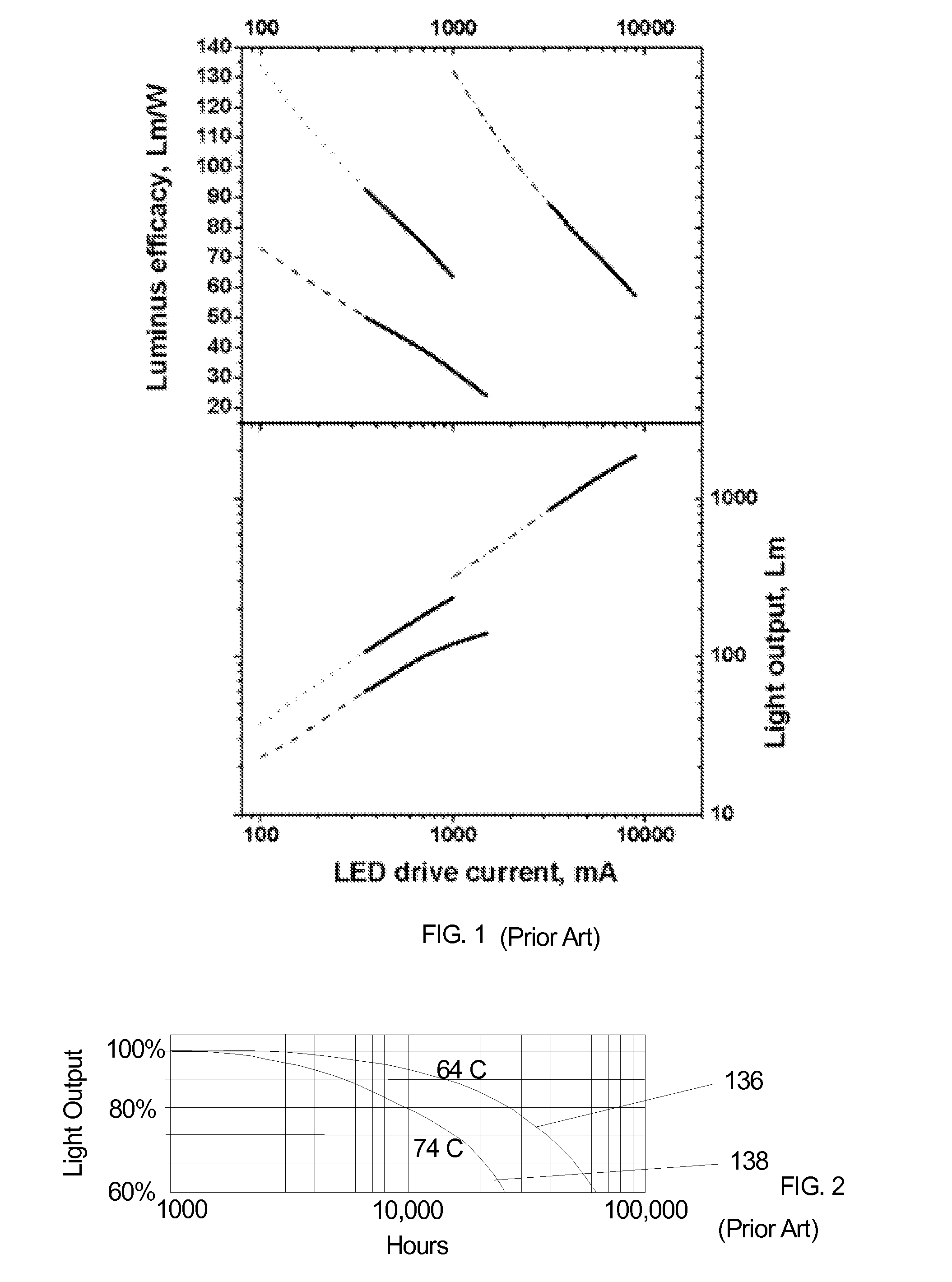
The problem with this approach is that the luminous efficacy of an individual LED decreases strongly with increasing drive current (for a given LED die size one may use a value of current and when comparing LED die of different sizes, one may choose to use either current or
current density).
At the low currents used to achieve the high luminous efficacy numbers, these devices produce relatively little light; certainly not enough to replace a single incandescent lamp.
Operation at higher current produces more light, but at the expense of significantly reduced luminous efficacy.
The data shown in FIG. 1 is taken with the LEDs maintained at 25° C. In actual operation maintaining such a low temperature is not possible and as the current increases, the LEDs operate at significantly higher temperatures, in the range of about 50° C. to about 100° C., which causes the luminous efficacy to drop further.
Another problem with the conventional
LED lamp approach of using high currents (
current density) is that the temperature rise associated with this mode of operation decreases the lifetime of an LED.
Driving an LED at relatively
high current densities and junction temperatures causes degradation mechanisms to accelerate.
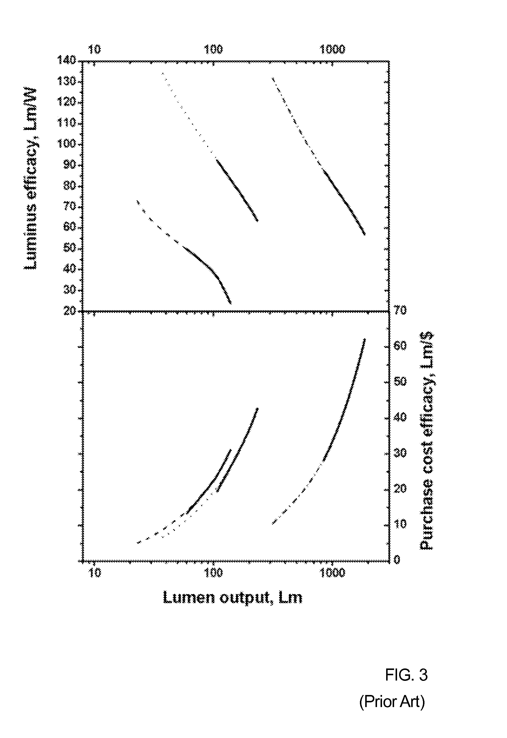
It is clear from this data that the
purchase cost efficacy (lm / $) increases rapidly with increased lumen output but this is at the expense of luminous efficacy.
This can be relatively expensive, and the cost increases when using higher and
higher power LEDs.
In addition to more expensive LED die, the LED
package cost increases as well.
As the LEDs are designed to operate at higher and higher temperatures, the packages for such LEDs become more complex and more expensive, in some cases costing more than the LED die itself.
Such packages are expensive, and the need to use multiple such packages in the lamp significantly increases the lamp cost.
Associated with this are the cost of the carrier or circuit board and the cost of attaching the LED packages to the circuit board or carrier, for example using solder.
The lamp cost is further increased because of the need for advanced thermal management systems required by operation at sub-optimal luminous efficacy values.
All of these factors act to decrease the LED lamp purchase cost efficacy, increase the total cost / unit time and decrease the lifetime of the lamp.
Each interface is associated with optical losses resulting from the difference in refractive indices of the materials forming the interface.
TIR light will suffer absorption losses within the die as it is reflected from various interfaces, leading to reduced light output and increased generation of heat.
Additional optical losses may also occur in lamps comprising a plurality of individual LEDs, for example packaged LEDs, arranged on a circuit board or carrier because of the increased etendue of the optical
system (etendue refers to how “spread out” the light is in area and angle).
In other words, as the dimensions of the light emitting area increase (the etendue increases) it becomes more difficult to focus and direct the light into a desired pattern without optical losses.
Lamps may also suffer further optical losses when put into a fixture.
LEDs typically operate in the range of about 2.5 to about 4 volts and when the number of the LEDs in the lamp is relatively low, the difference in LED
voltage and the input
voltage is relatively large, resulting in a relatively low efficiency.
While the
electronics efficiency may be able be improved with respect to both output
voltage and dissipated heat for conventional LED lamps, this may lead to unacceptable increases in the
electronics form factor and cost.
As discussed above, prior-art LED lamps comprising one or more packaged LEDs driven at relatively high currents and
high current densities generate significant heat because of their low luminous efficacy.
As the temperature is increased, the light output of LEDs is reduced, thus further reducing the luminous efficacy.
It can be seen that the LED lamps produce significantly more visible light power than incandescent lamps, but still produce a significant amount of heat which must be managed appropriately.
Typically this means higher operating temperatures and more expensive packaging and thermal management techniques.
However, conventional LED lamps are very expensive ($80-$120 per lamp) and thus, as discussed previously, even though the electricity costs are typically about ¼ to about ½ that of incandescent lamps, the high first cost is sufficient to prevent widespread adoption.

