Redundant backlight for liquid crystal displays

a liquid crystal display and backlight technology, applied in static indicating devices, instruments, optical elements, etc., can solve the problems of poor performance of lcd, long time consumption, and the inability to meet the requirements of lighting conditions, etc., to achieve low wattage, reduce heat generation, and improve efficiency

Inactive Publication Date: 2012-06-14
AMERICAN PANEL CORP INC
View PDF11 Cites 9 Cited by
  • Summary
  • Abstract
  • Description
  • Claims
  • Application Information

AI Technical Summary

Benefits of technology

[0013]The system may include a device for monitoring the luminance produced by the first and/or second array of LEDs. The monitoring device may include predetermined operational standards for the display. When the monitoring device detects that the display has fallen below the predetermined standard for luminance, the monitoring system may send a signal to one or both control modules. If the first array of LEDs were the only source of illumination, the control modules can then switch to the second array of LEDs as there may have been a failure in the first array. The second or redundant set of LEDs can be utilized seamlessly, thus en

Problems solved by technology

The light which is passing through each subpixel typically originates as “white” (or broadband) light from the backlight, although in general this light is far from being uniform across the visible spectrum.
When used for extended periods of time and/or outdoors, durability of the components especially the illumination sources such as LEDs can become an issue.
If the backlight system should fail completely or operate at a less than optimal level, then the LCD will not perform satisfactorily.
While this may be a simple inconvenience when LCDs are used for entertainment purposes, when used for information or data displays this can be very costly.
In these applications, when there is a failure of the backlight, the LCD may no longer display the important information for the vehicle/aircraft and controls may cease to operate.
These si

Method used


Image

  • Redundant backlight for liquid crystal displays
  • Redundant backlight for liquid crystal displays
  • Redundant backlight for liquid crystal displays

Examples


embodiment 200

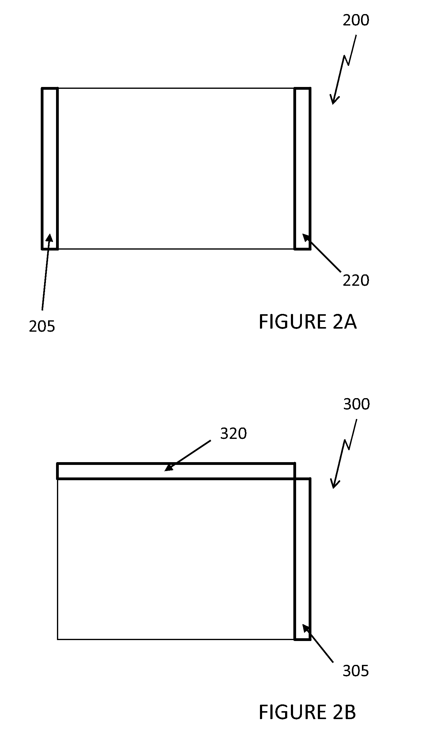
[0025]FIG. 2A shows an alternative embodiment using an edge-lit LED backlight 200. As known in the art, edge-lit LED backlights place the LEDs along one of the edges of the backlight so that they can provide illumination into the backlight cavity. This illumination is typically directed out of the backlight cavity and through the LCD stack as well as scattered and / or diffused to provide a uniform light distribution. The scattering and directing of the light can be accomplished in a number of different ways (light guides, diffusing sheets, etc.) and the details of this will not be discussed in detail as it is well known in the art. For the edge-lit embodiment 200, the first plurality of LEDs 205 are placed along a first edge while the second plurality of LEDs 220 are placed along the opposing edge of the backlight. This design is beneficial in an embodiment where both sets of LEDs are operated simultaneously as they could combine evenly to create a uniform distribution of light. Agai...

embodiment 400

[0027]FIG. 3A shows a front view for an embodiment 400 using edge LED backlighting for an LCD where the both opposing sides of the LCD are illuminated. Here, a first set of LEDs is comprised of two arrays of LEDs 431 and 430 which are placed on opposing sides of the LCD. Additionally, a second set of LEDs is comprised of two arrays of LEDs 420 and 421 which are placed on opposing sides of the LCD.

embodiment 450

[0028]FIG. 3B shows a front view for an embodiment 450 using a combination of edge LED backlighting and direct LED backlighting. Here, a first set of LEDs may be provided in edge-lit fashion such that LEDs 461 are along a first edge with LEDs 460 along an opposing edge. Additionally, a second set of LEDs 480 is provided in a direct lit fashion.

[0029]FIG. 4 provides an electrical schematic for an exemplary embodiment. A first controller 515 is in electrical communication with a first current source 510 which drives the first set of LEDs 505. A second controller 530 is in electrical communication with a second current source 525 which drives the second set of LEDs 520. The electrical connection 575 provides communication between the first controller 515 and second controller 530. The first and second controllers 515 and 530 may be any type of microprocessor, application-specific integrated circuit, complex programmable logic device, field-programmable gate array, or any other form of ...


PUM


Abstract

A redundant LED backlight and method for controlling the same. At least two plurality of LEDs are used to create a backlight where any individual set of LEDs may be driven at power level P to provide the desired overall luminance for the backlight. If two plurality of LEDs are used, then the LEDs may be driven simultaneously at one-half P during normal operations until a failure has been detected in one of the plurality of LEDs. In alternate embodiments, four plurality of LEDs may be used and driven simultaneously at one-fourth P during normal operations until a failure has been detected in one of the plurality of LEDs. The LEDs may be in edge-lit, direct-lit, or any combination of these two orientations. Upon failures, only one plurality of LEDs may be used to provide operation of the LED backlight and any associated LCD device.

Description

CROSS-REFERENCE TO RELATED APPLICATIONS[0001]This application claims priority to U.S. Application No. 61 / 353,986, filed Jun. 11, 2010, titled Redundant Backlight for Liquid Crystal Displays, which is incorporated herein by reference.TECHNICAL FIELD[0002]Disclosed embodiments relate generally to an LED backlight system for a liquid crystal display device.BACKGROUND OF THE ART[0003]Liquid Crystal Displays (LCDs) contain several layers which work in combination to create a viewable image. A backlight is used to generate the rays of light that pass through what is commonly referred to as the LCD stack, which typically contains several layers that perform either basic or enhanced functions. The most fundamental layer within the LCD stack is the liquid crystal material, which may be actively configured in response to an applied voltage in order to pass or block a certain amount of light which is originating from the backlight. The layer of liquid crystal material is divided into many smal...

Claims


Application Information

Patent Timeline
IPC IPC(8): H05B37/02G02F1/13357
CPCG09G3/3406G02F1/133603G09G2330/08G02B6/0061G02B6/0068G02B6/0073G09G3/3426G09G2320/0233G09G2320/0626G09G2360/16
Inventor DUNN, WILLIAM
Owner AMERICAN PANEL CORP INC
Why Eureka
Try Eureka