Power converting apparatus, grid interconnection apparatus and grid interconnection system
a technology of grid interconnection and power converting apparatus, which is applied in the direction of electric variable regulation, process and machine control, instruments, etc., can solve the problems of increasing efficiency, reducing efficiency, and reducing the size of the dc-dc converter circuit, so as to reduce the size and increase the efficiency. , the effect of reducing the cos
- Summary
- Abstract
- Description
- Claims
- Application Information
AI Technical Summary
Benefits of technology
Problems solved by technology
Method used
Image

Examples
first embodiment
[0040]In the following, a grid interconnection apparatus according to a first embodiment will be described in the order of (1) Schematic Structure, (2) Main Circuit, (3) Control Unit and (4) Operation and Effect.
(1) Schematic Structure
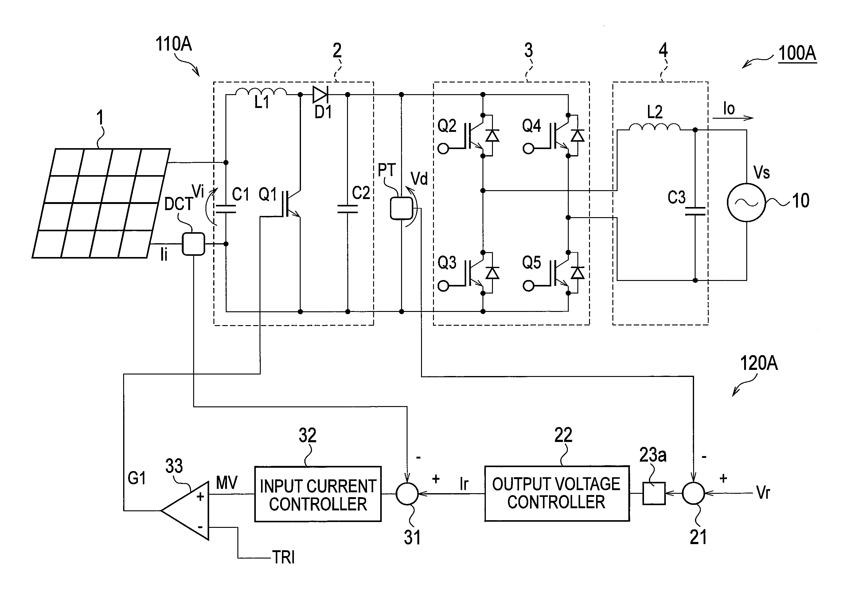
[0041]FIG. 1 is a configuration diagram of a grid interconnection system provided with a grid interconnection apparatus 100A according to the first embodiment.
[0042]The grid interconnection system illustrated in FIG. 1 is provided with a solar cell 1, a grid interconnection apparatus 100A and a distribution system 10. The solar cell 1 is a distributed type distributed power supply which outputs DC power produced by power generation in accordance with sunlight irradiation.
[0043]The grid interconnection apparatus 100A converts DC power from the solar cell 1 into AC power of the commercial frequency (for example, 50 Hz or 60 Hz). Load (not illustrated) installed in a consumer is connected between the grid interconnection apparatus 100A and the distributio...
second embodiment
[0093]In the second embodiment, a configuration in which a voltage detector PT is provided with a function of a low-pass filter will be described. FIG. 5 is a configuration diagram of a grid interconnection system provided with a grid interconnection apparatus 100D according to the second embodiment.
[0094]As illustrated in FIG. 5, a voltage detector PT′ according to the second embodiment is connected subsequent to a step-up chopper circuit 2 between a positive side line L1 and a negative side line L2. A detected value output from the voltage detector PT′ is a value from which a ripple component included in an output voltage Vd has been removed.
[0095]FIG. 6 is a circuit configuration diagram of the voltage detector PT′. As illustrated in FIG. 6, the voltage detector PT′ is provided with two resistors R1 and R2 connected in series between the positive side line L1 and the negative side line L2, and a condenser C4 connected between a junction point of the resistors R1 and R2 and the ne...
third embodiment
[0099]FIG. 7 is a configuration diagram of a grid interconnection system provided with a grid interconnection apparatus 100E according to a third embodiment.
[0100]The third embodiment differs from the first embodiment in a connecting location of a current detector DCT in a main circuit 110E. The current detector DCT is connected preceding the reactor Li. A control unit 120E is configured in the same manner as that of the first embodiment.
[0101]The current detector DCT detects a reactor input current IL. An error calculator 31 generates an error signal indicating an error between a reactor input current IL detected by the current detector DCT and a target current value Ir.
[0102]The input current controller 32 generates a chopper manipulated variable MV from that error signal. The PWM comparator 33 generates the gate signal G1 on the basis of a comparison result of a standard triangular wave TRI and the chopper manipulated variable MV.
[0103]Since the low-pass filter 23a removes a ripp...
PUM
 Abstract
Description
Claims
Application Information
 - R&D
- Intellectual Property
- Life Sciences
- Materials
- Tech Scout
- Unparalleled Data Quality
- Higher Quality Content
- 60% Fewer Hallucinations
Browse by: Latest US Patents, China's latest patents, Technical Efficacy Thesaurus, Application Domain, Technology Topic, Popular Technical Reports.
© 2025 PatSnap. All rights reserved.Legal|Privacy policy|Modern Slavery Act Transparency Statement|Sitemap|About US| Contact US: help@patsnap.com