On-site Fabricated Fiber-Composite Floating Platforms for Offshore Applications

a technology of floating platforms and fiber composites, which is applied in the direction of vessels, machines/engines, transportation and packaging, etc., can solve the problems of not being able to provide some of the benefits of vertical fabrication, no other process known to the inventor is capable of producing multi-shot, continuous fiber composites,

Active Publication Date: 2012-06-21
LOCKHEED MARTIN CORP
View PDF36 Cites 9 Cited by
  • Summary
  • Abstract
  • Description
  • Claims
  • Application Information

AI Technical Summary

Benefits of technology

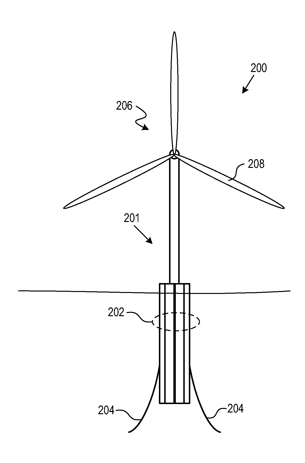
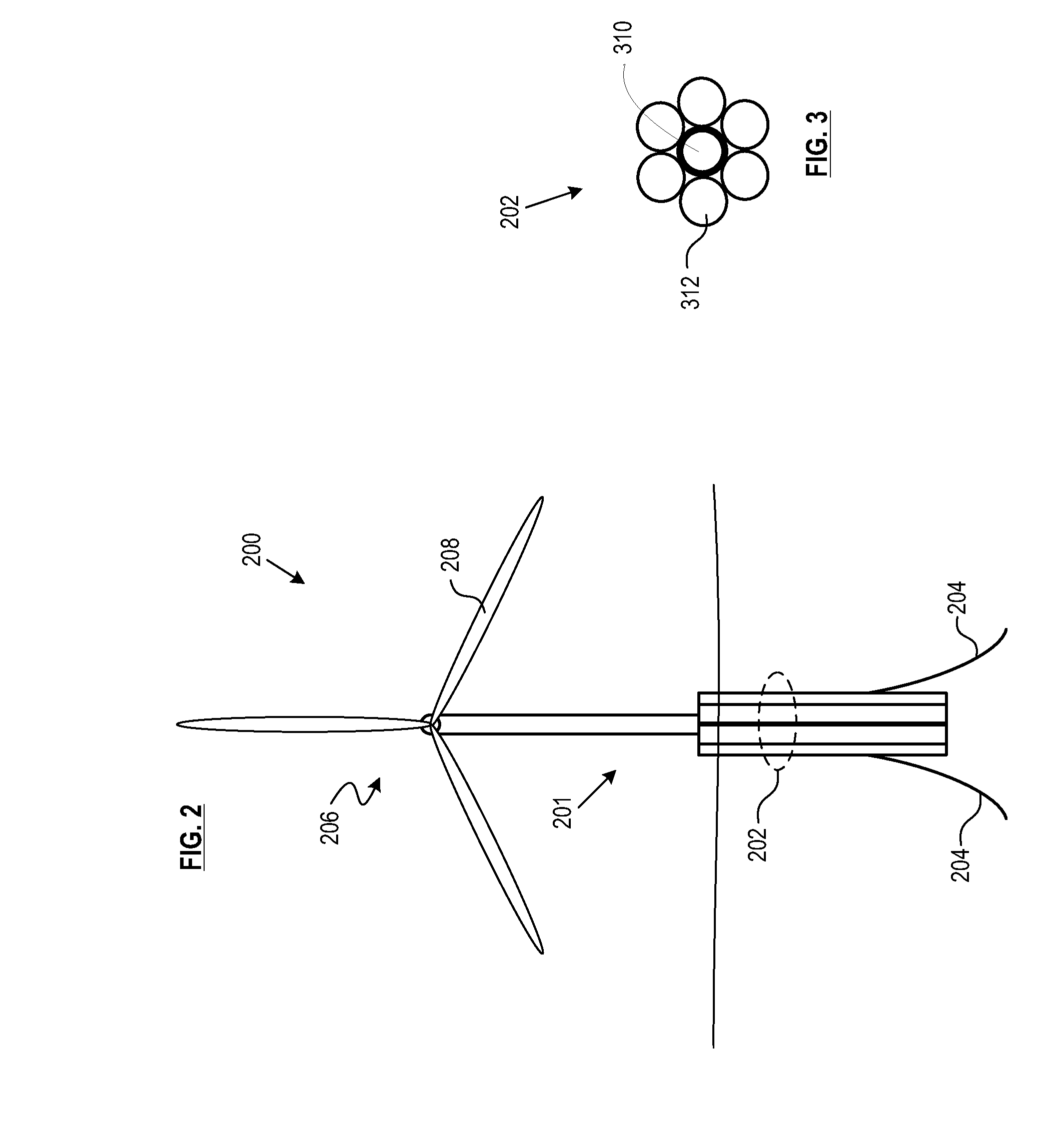
[0029]In some embodiments, the spar platform comprises a total of seven tubes arranged so that six peripheral tubes surround one central tube. The central tube is typically longer and thicker-walled than the peripheral tubes. The longer central tube will typically require multiple molding runs or shots. Using the referenced modified VARTM process, at least the central tube will be formed as a continuous-fiber composite and exhibit benefits derived theref

Problems solved by technology

Relative to land-based or shallower offshore sites, these locations require relatively higher capital investment due to the costs of towing the shipyard-fabricated equipment to the offshore site, deploying it at site, and mooring it.
No other process known to the inventor is capable of producin

Method used


Image

  • On-site Fabricated Fiber-Composite Floating Platforms for Offshore Applications
  • On-site Fabricated Fiber-Composite Floating Platforms for Offshore Applications
  • On-site Fabricated Fiber-Composite Floating Platforms for Offshore Applications

Examples


Embodiment Construction

[0049]Definitions. The terms appearing below are provided with the follow explicit definitions for use in this description and the appended claims.[0050]Continuous-fiber composite means a fiber composite in which fibers are continuous throughout that the composite, as opposed to being chopped or short (i.e., discontinuous).[0051]Shot refers to the amount of resin that is required to fill a mold cavity. A “multi-shot” article requires multiple, sequential resin fills and cures within the mold cavity.[0052]Workpiece means the structure that is produced or the assemblage (e.g., core, fiber, resin) that will form that structure in a single shot in the molding region. In the context of multi-shot articles, the workpiece therefore represents a portion or segment of the final composite article (e.g., a segment of the cold water pipe, etc).[0053]Continuity of fiber means that there is no discontinuity or break in fibers between the workpieces that compose a multi-shot composite article. To ...


PUM

PropertyMeasurementUnit
Lengthaaaaaaaaaa
Thicknessaaaaaaaaaa

Abstract

A spar platform comprises one or more continuous-fiber composite tubes fabricated at or near the intended site use of the platform. In some embodiments, the spar platform includes a relatively longer central tube and relatively shorter peripheral tubes. In some other embodiments, the spar platform is a single long tube. In some embodiments, the spar platform supports a wind turbine assembly. The continuous-fiber composite tubes are formed, in either a vertical or horizontal orientation, using a modified vacuum assisted resin transfer molding process.

Description

STATEMENT OF RELATED APPLICATIONS[0001]This case claims priority to U.S. Provisional Patent Application Ser. No. 61 / 425,548, which was filed on Dec. 21, 2010 and is incorporated by reference herein.FIELD OF THE INVENTION[0002]The present invention relates to offshore floating platforms.BACKGROUND OF THE INVENTION[0003]Wind power has been in use by humans for thousands of years. Windmills have been used for irrigation, pumping, and milling grain since the 7th Century A.D. and wind has been propelling sailing ships since well before 3000 B.C. By the late 19th Century, the first electricity-producing, wind-powered machines were developed.[0004]The modern wind-power industry began in the late 1970s. In modern installations, referred to as “wind farms,” multiple individual wind turbines are interconnected via a medium-voltage power-collection system and communications network. At a substation, this medium-voltage current is stepped up in voltage for connection to the high-voltage electri...

Claims


Application Information

Patent Timeline
IPC IPC(8): E02D5/74
CPCB63B9/065B63B5/24B63B35/44F03D11/045B63B2009/067Y02E10/727B63B2035/446B63B2231/52F05B2240/93F05B2240/95F05B2280/6003B63B2035/442B63B75/00B63B77/10F03D13/22F03D13/25Y02E10/72
Inventor NAGURNY, NICHOLAS J.MILLER, ALAN K.
Owner LOCKHEED MARTIN CORP
Why Eureka
Try Eureka