Ultrasound probe and ultrasound examination device using the same
- Summary
- Abstract
- Description
- Claims
- Application Information
AI Technical Summary
Benefits of technology
Problems solved by technology
Method used
Image

Examples
embodiment 1
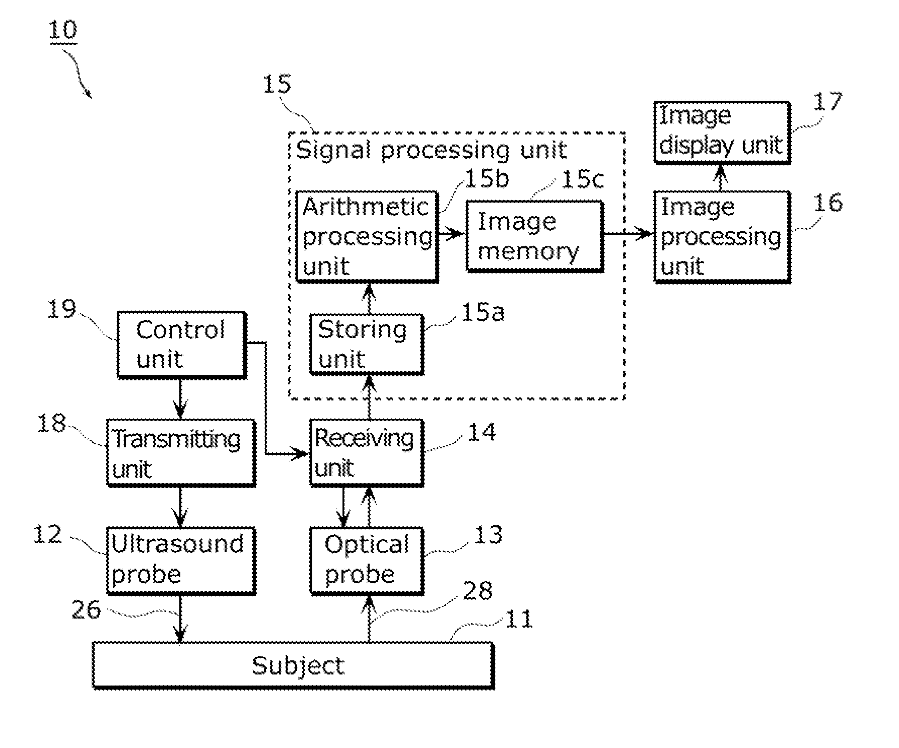
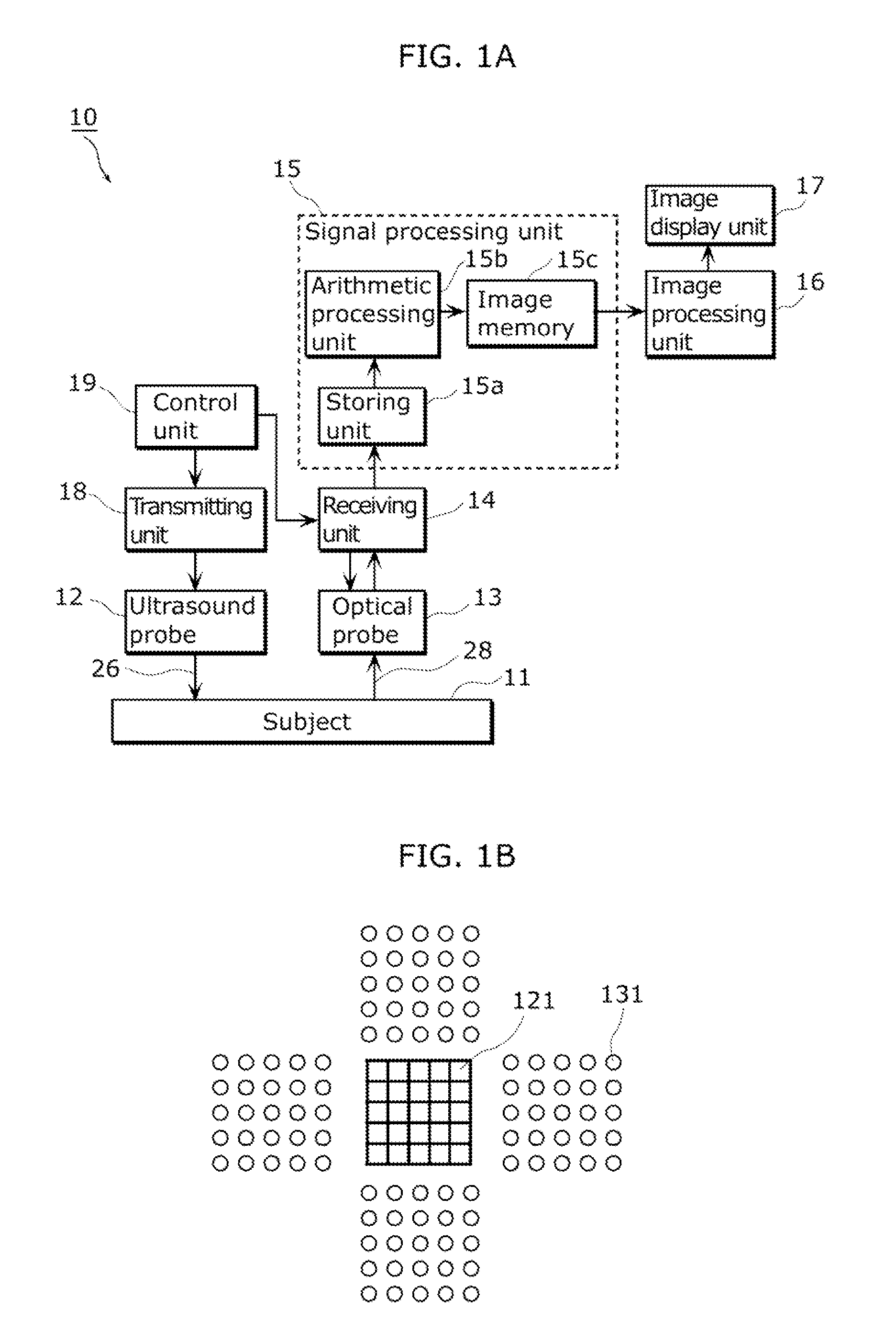
[0077]FIGS. 1A and 1B show a schematic configuration of an ultrasound examination device 10 in Embodiment 1 of the present invention. FIG. 1A is a block diagram showing the configuration, and FIG. 1B shows arrangement of points that transmit and receive ultrasound waves in a probe for examination in the ultrasound examination device 10.
[0078]The ultrasound examination device 10 includes: an ultrasound probe 12 that transmits the ultrasound waves to a subject 11; an optical probe 13 that detects micro vibration of a surface of the subject 11 with use of light, modulates such information, and outputs the resultant information; a receiving unit 14 that amplifies a detection signal obtained by demodulating an output signal of the optical probe 13, applies digital conversion to the detection signal, and outputs the resultant signal; a signal processing unit 15 that performs phasing addition, such as digital beam forming, using the signal outputted from the receiving unit 14; an image pro...
embodiment 2
[0148]While Embodiment 1 describes an example in which the optical probe is composed of the heterodyne optical system, Embodiment 2 describes an example in which the optical probe is composed of the Fabry-Perot resonator structure.
[0149]FIGS. 11A and 11B each show configurations of an optical probe and a receiving unit in Embodiment 2 of the present invention. FIG. 11A shows a configuration in which the light source 221 and the light-receiving element are disposed inside an optical probe 213, and FIG. 11B shows a configuration in which the light source221 and the light-receiving element, i.e., a light detector 225, are disposed inside the device main body, i.e., a receiving unit 214, of the ultrasound examination device (the ultrasound diagnostic device). Here, FIG. 11B shows a specific configuration example of the configuration shown in FIG. 11A. This means that the configuration and operation in FIG. 11A are the same as those in FIG. 11B except that illuminating light and detectio...
embodiment 3
[0187]Embodiment 2 has described that the optical probe which has the Fabry-Perot resonator structure and includes the ultrasound detection element having the sound matching material detects the ultrasound echoes with use of the deformation of the sound matching material caused by the ultrasound echoes. Embodiment 3 describes an example of the case where, although the optical probe has the Fabry-Perot resonator structure, the ultrasound detection element includes an acoustic lens, an acoustic mirror, or the like as the sound matching material.
[0188]FIGS. 14A and 14B each illustrate a variation of a configuration of the ultrasound detection element in Embodiment 3 of the present invention. Constituents which are the same or like as those in FIG. 12A are denoted with the same signs and will not be described in detail.
[0189]FIG. 14A shows a configuration example which uses an acoustic lens 351, and FIG. 14B shows a configuration example which uses an acoustic mirror 361. In FIGS. 14A a...
PUM
 Abstract
Description
Claims
Application Information