Cooler having ground heated plane for cooling heating electronic component

a technology of electronic components and cooling planes, which is applied in the field of cooling devices with ground heated planes, can solve the problems of reducing operation efficiency, overheating of electronic components, and increasing power consumption, so as to improve the effect of thermal conduction, improve the flatness and surface roughness, and improve the contact tightness between the heated plane and the heating electronic components

Inactive Publication Date: 2012-06-28
LIN KUO LEN +4
View PDF6 Cites 1 Cited by
  • Summary
  • Abstract
  • Description
  • Claims
  • Application Information

AI Technical Summary

Benefits of technology

[0009]The invention is mainly to provide a cooler with ground heated plane and a grinding method and apparatus thereof. By grinding the heated plane of the cooler, the roughness and flatness on the surface of the heated plane is improved. Furthermore, the thermally conductive effect is enhanced due to a better contact relative to the heating electronic component.
[0013]Compared with the prior arts, the invention is to arrange a fixture to a grinder. The fixture presses and clamps a cooler via a point contact manner, whereby the heated plane of the cooler can possess a better flatness and surface roughness after being ground. Therefore, the contact tightness between the heated plane and the heating electronic component is increased, further generating a better effect of thermal conduction and enhancing the practicability of the invention.

Problems solved by technology

Following progress of technology, computer hardware is developed toward the directions of high speed and high frequency for increasing its execution efficiency, but its power consumption is also increased relatively.
If the accumulative heat is not removed in time, the electronic component will be overheated to lower down the operation efficiency, even cause damage.
However, since of the limitation of many factors, such as cooling space and power consumption, how to promote cooling efficiency as high as we can becomes an issue intended to be addressed urgently by industry.
However, in practice, the roughness and flatness on the surface of the heated face is still poor, making the heated face and the heating component unable to be contacted closely, thereby, limiting the thermal conduction between the heated face and the heating electronic component.

Method used


Image

  • Cooler having ground heated plane for cooling heating electronic component
  • Cooler having ground heated plane for cooling heating electronic component
  • Cooler having ground heated plane for cooling heating electronic component

Examples


Embodiment Construction

[0026]In cooperation with attached drawings, the technical contents and detailed description of the present invention are described thereinafter according to a number of preferable embodiments, not used to limit its executing scope. Any equivalent variation and modification made according to appended claims is all covered by the claims claimed by the present invention.

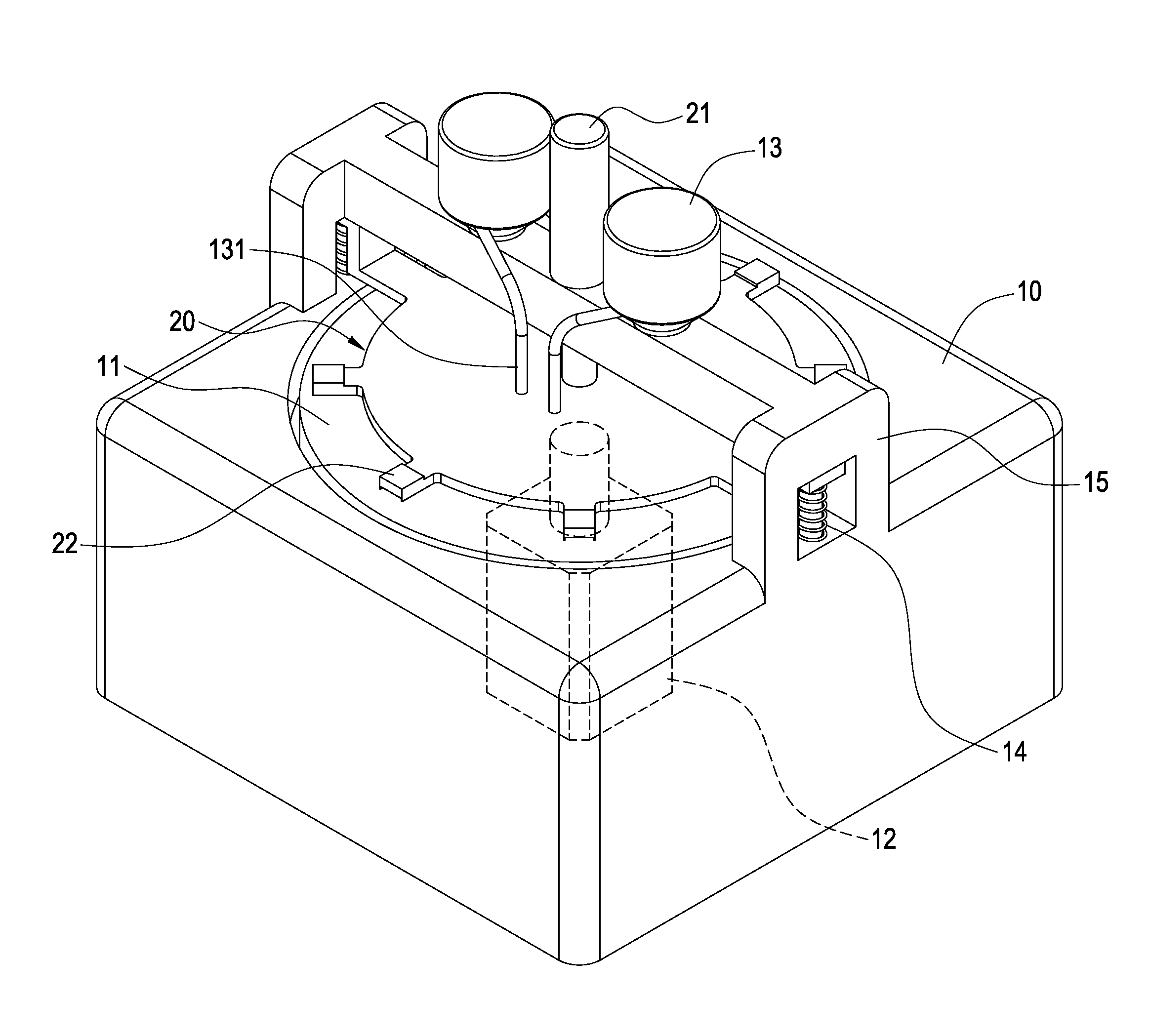
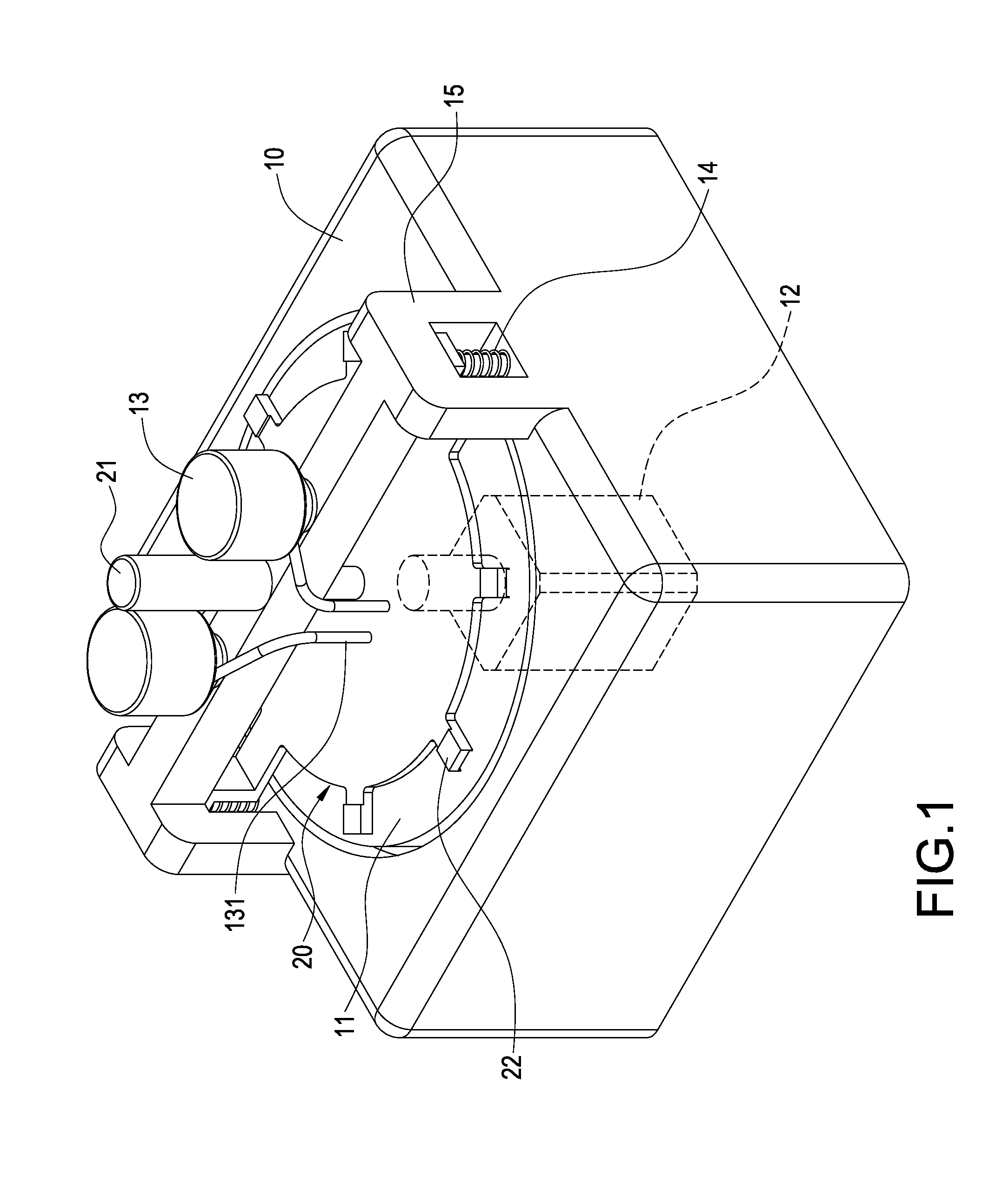
[0027]Please refer to FIG. 1, which is an assembled illustration of a grinder and a fixture according to the present invention. The invention is to provide a method for grinding the heated plane of a cooler, in which a grinder 10 having grinding plate 11 and fixing frame 15 is provided. The grinding plate 11 is actuated by a motor 12 to rotate. The fixing frame 15 is fixed onto the grinder 10 and is arranged an abrasive supply barrel 13 thereon. The abrasive supply barrel 13 is filled with abrasive and has a nozzle 131 to inject the abrasive onto the grinding plate 11.

[0028]Above the grinding plate 11, the grinder 10 i...


PUM


Abstract

A method for making heated plane of a cooler to obtain better flatness and roughness includes a grinder with a grinding plate and a fixture. Then, the cooler is arranged onto the fixture. Next, the abrasive is injected into the gap between the grinding plate and the heated plane, making the fixture press and clamp the cooler in a way, such that the heated plane of the cooler contacts the abrasive closely. Finally, the grinding plate is rotated to make at least one grinding process to the heated plane, making the heated plane obtain a surface with better roughness and flatness, further enhancing the contact tightness between the heated plane and a heating element, and therefore promoting the thermally conductive efficiency between the cooler and the heating element.

Description

CROSS-REFERENCE TO RELATED APPLICATIONS [0001]This application is a divisional application of U.S. application Ser. No. 12 / 482,000 filed on Jun. 10, 2009. The entire disclosure is incorporated herein by reference.BACKGROUND OF THE INVENTION [0002]1. Field of the Invention[0003]The present invention in general relates to a cooler, in particular, to a cooler, a heated plane of which is ground, and to a grinding method thereof.[0004]2. Description of Prior Art[0005]Following progress of technology, computer hardware is developed toward the directions of high speed and high frequency for increasing its execution efficiency, but its power consumption is also increased relatively. Compared to the prior arts, the heat generated from today's electronic component is much more significant than the past's. If the accumulative heat is not removed in time, the electronic component will be overheated to lower down the operation efficiency, even cause damage. So, most electronic component needs co...

Claims


Application Information

Patent Timeline
Patent Type & Authority Applications(United States)
IPC IPC(8): F28D15/04B24B57/02B24B37/04B24B37/30B24B41/06F28D15/02H01L23/427H05K7/20
CPCF28D15/0233F28D15/0275F28F13/182H01L23/427H01L23/467B24B37/04H01L2924/0002B24B37/30B24B57/02B24B37/12H01L2924/00
Inventor LIN, KUO-LENLIN, CHEN-HSIANGLIU, JUI-HOCHENG, CHIH-HUNGHSU, KEN
Owner LIN KUO LEN
Why Eureka
Try Eureka