Mirror And A Method Of Manufacturing Thereof

Inactive Publication Date: 2012-06-28
VANGUARD SPACE TECH
View PDF10 Cites 4 Cited by
  • Summary
  • Abstract
  • Description
  • Claims
  • Application Information

AI Technical Summary

Benefits of technology

[0007]A mirror comprises a substrate having a first surface and an opposed second surface. The substrate is of a material having thermo-mechanical stability, low mass and stiffness for providing a shape to the mirror. A front non-specular buffer layer is immediately adjacent to and contiguous with the substrate on the first surface. The front buffer layer is a of a material to buffer the surface morphology of the first surface of the substrate. A front specularizing layer is immediately adjacent to and contiguous with the front buffer layer. The specularizing layer is of a m

Problems solved by technology

The thickness of the resin layer depends on the level of local roughness and large scale contour errors, which results in differences between the substrate front surface and the mandrel which the replication resin fills in.
The disadvantage of using the direct replication method is that the resin has to be relatively thick, on the order of 0.5 mm or more, and can crack and degrade when exposed to thermal and humidity cycling across the temperature and humidity ranges of terrestrial and aerospace applications.
Another disadvantage of the direct replication approach is the need to get good, bubble-free co

Method used


Image

  • Mirror And A Method Of Manufacturing Thereof
  • Mirror And A Method Of Manufacturing Thereof

Examples


Example

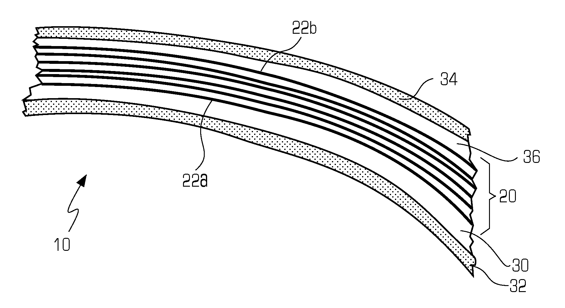
[0012]Referring to FIG. 2 there is shown a cross-sectional view of a mirror 10 of the present invention. The mirror 10 comprises a substrate 20. The substrate 20 has a first surface 22a and a second surface 22b, opposite the first surface 22a. The substrate 20 serves to provide the shape or contour of the mirror 10. The contour can be spherical, aspherical, cylindrical, cylindrical aspheric, planar, or any other shape. The substrate 20 is of a material which provides thermo-mechanical stability, low mass, and stiffness. It can be made from metals, composite sandwich structures, plastic or in the preferred embodiment Graphite Fiber Reinforced Composite (GFRC). In the preferred embodiment, the substrate 20 is a six layer GFRC laminate composite in which the plies or layers are uni-directional plies, arranged in a sequential direction layup to provide quasi-isotropic properties and a balanced laminate, such as (0 / 60 / −60 / −60 / 60 / 0) with each ply comprising a 0.04 mm layer of graphite fib...


PUM

PropertyMeasurementUnit
Moldableaaaaaaaaaa
Shapeaaaaaaaaaa
Stabilityaaaaaaaaaa

Abstract

A mirror for terrestrial or aerospace application has a substrate, which is preferably of a laminate of a plurality of Graphite Fiber Reinforced Composite (GFRC) uni-directional fiber plies applied in a laminate with layers oriented to achieve appropriate stable properties. The substrate is cured to form the desired shape with a first surface and a second surface opposite the first surface. A front buffering layer is immediately adjacent to and contiguous with the substrate on the first surface. The front buffer layer is of a material that buffers the surface morphology of the first surface of the substrate. A front specularizing layer is immediately adjacent to and contiguous with the front buffer layer. The specularizing layer is of a material for providing a smooth, low scatter optical surface. The specularizing layer can use an integral aluminized surface or an added vacuum deposited optical thin film coating for enhanced optical properties and durability. The mirror further has a rear buffering layer which is immediately adjacent to and contiguous with the second surface of the substrate. Finally, the mirror has a rear film which is immediately adjacent to and contiguous with the buffering layer. The material for the rear buffering layer can be the same material as that for the front buffering layer, and the material for the rear film can be the same material as that for the front specularizing layer, so as to balance the Coefficient of Thermal Expansions (CTE) of the front layers.

Description

TECHNICAL FIELD[0001]The present invention relates to a mirror and, more particularly, to a mirror that is well suited for deployment and use in harsh terrestrial and aerospace environments. The present invention also relates to a method of manufacturing such a mirror.BACKGROUND OF THE INVENTION[0002]Mirrors or optical apparatuses to reflect, focus or concentrate impinging electromagnetic radiation are well known in the art. At least three of the properties that a mirror must have are that the optical surface must have an accurate contour, that the optical surface be specular (smooth or polished) and that the optical surface reflects the appropriate electromagnetic radiation. Although mirrors have been manufactured for use in terrestrial applications as well as outer space applications, for extra-terrestrial application, the mirror must withstand other environments such as UV radiation, temperature cycling, temperature gradient, contamination, self contamination, and the impact of p...

Claims


Application Information

Patent Timeline
IPC IPC(8): G02B1/10B29C70/30
CPCB29C70/30G02B5/0808B29L2011/0058B29D11/00596
Inventor STERN, THEODORE GARRYENGELSON WYATT, STEPHEN LEONARD
Owner VANGUARD SPACE TECH
Why Eureka
Try Eureka