
Antifriction bushing

a technology of anti-friction bushings and bushings, which is applied in the direction of bearings, shafts, engine lubrication, etc., can solve the problems of inability to achieve lasting satisfaction, unacceptable noise development of motor vehicle steering mechanisms, and improvement proposals in these publications, so as to improve anti-friction properties and reduce the cost of parts production

Active Publication Date: 2012-06-28
THYSSENKRUPP PRESTA AG
View PDF8 Cites 14 Cited by
  • Summary
  • Abstract
  • Description
  • Claims
  • Application Information

AI Technical Summary

Benefits of technology

[0012]The present invention therefore addresses the problem of providing an antifriction bushing or a telescopable steering spindle with permanently improved antifriction properties, wherein the expenditure for the production of the parts is decreased.
[0014]The use of an antifriction bushing according to the invention has the advantage that a sliding connection is produced between the structural elements, and the connection has a long service life and sustainably reduces the stick-slip effect.
[0015]By PEEK is understood the synthetic material polyether ether ketone or a derivative from the group of polyaryl ether ketones. However, polyether ether ketone is to be preferably used as the PEEK. As already stated above, by PTFE is to be understood polytetrafluoroethylene. The term coal-substance [DE] or carbon fiber is also known by the names carbon fiber [UK] or coal [DE] fiber. Admixing at least one of the materials PTFE, graphite and / or carbon fibers leads to the lowering of the static friction while maintaining the service life. The unexpected effect to the person of skill in the art lays in that the difference between static and kinetic friction can also be decreased.
[0016]The antifriction bushing is preferably formed of a mixture of the material PEEK and additionally the material PTFE at a volume percentage in the range of 7% to 13% and additionally the material graphite at a volume fraction of 7% to 13% and additionally carbon fibers at a volume fraction of 25% to 35%, and further materials can also be comprised in the mixture. The combination of the materials increases the service life of the antifriction bushing and the sliding connection formed therewith. It has been found to be especially advantageous to realize the antifriction bushing of a mixture which comprises the material PEEk as well as PTFE at a volume fraction of 10% and graphite at a volume fraction of 10% and carbon fibers at a volume fraction of 30% or consists entirely of these materials. Such synthetic materials are basically known and commercially available.
[0020]It was entirely unexpected to find that a lubricant with such a low dynamic viscosity is suitable to contribute to minimization of the step difference between static and kinetic friction.
[0022]To improve the adhesion of the lubricant in the region of the sliding contact, the sliding partner of steel with a surface roughness of Ra (=arithmetic mean roughness value) in the range of 0.2 μm to 0.6 μm is suitable. Accordingly, the outer spindle and / or the inner spindle is produced of the material steel. On its surface facing the bushing, roughness values Ra in the range of 0.2 μm to 0.6 μm, preferably in the vicinity of 0.4 μm, are realized.

Problems solved by technology

During small movements, this effect causes a force peak in the axial direction due to the difference between static friction and kinetic friction, which peak leads to unacceptable noise development in motor vehicle steering mechanisms.
In telescopable steering spindles according to the prior art, this is not achieved to lasting satisfaction.
The improvements proposed in these publications, however, are cost-intensive and complex and to some extent require additional work steps and do not always contribute to a long service life.

Method used


Image

  • Antifriction bushing
  • Antifriction bushing
  • Antifriction bushing

Examples


Embodiment Construction

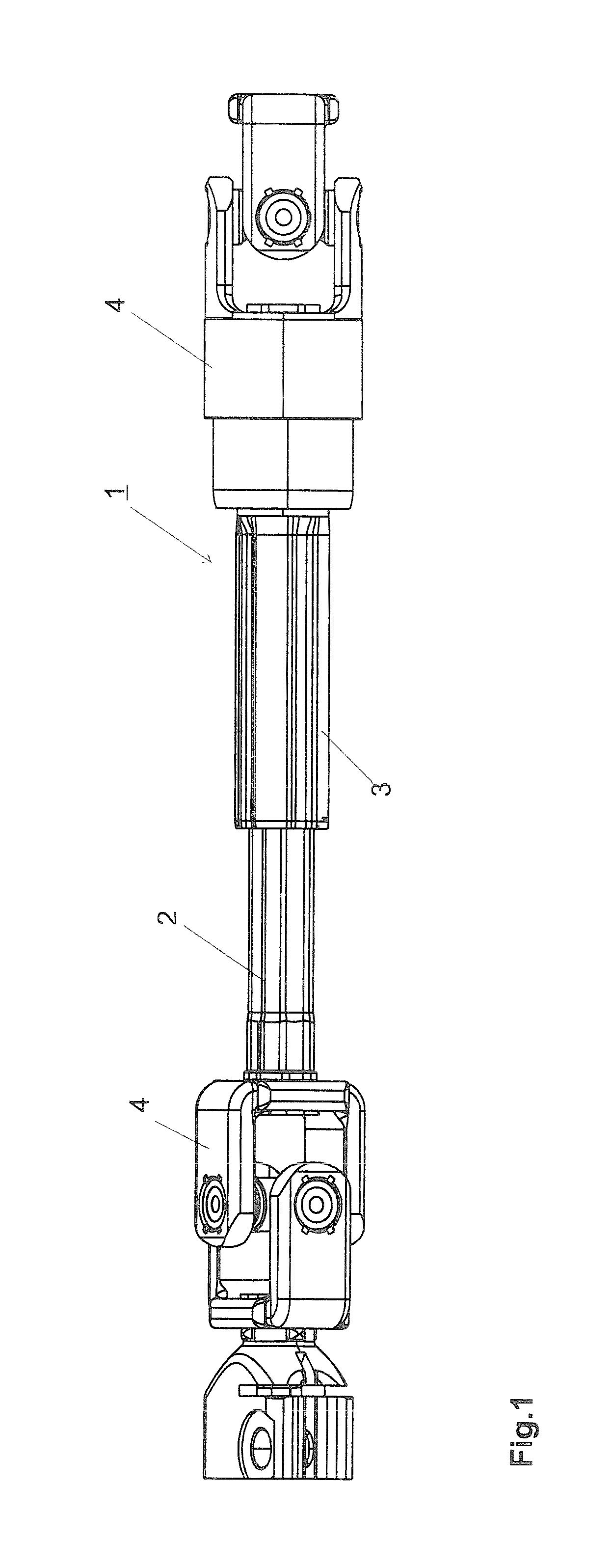
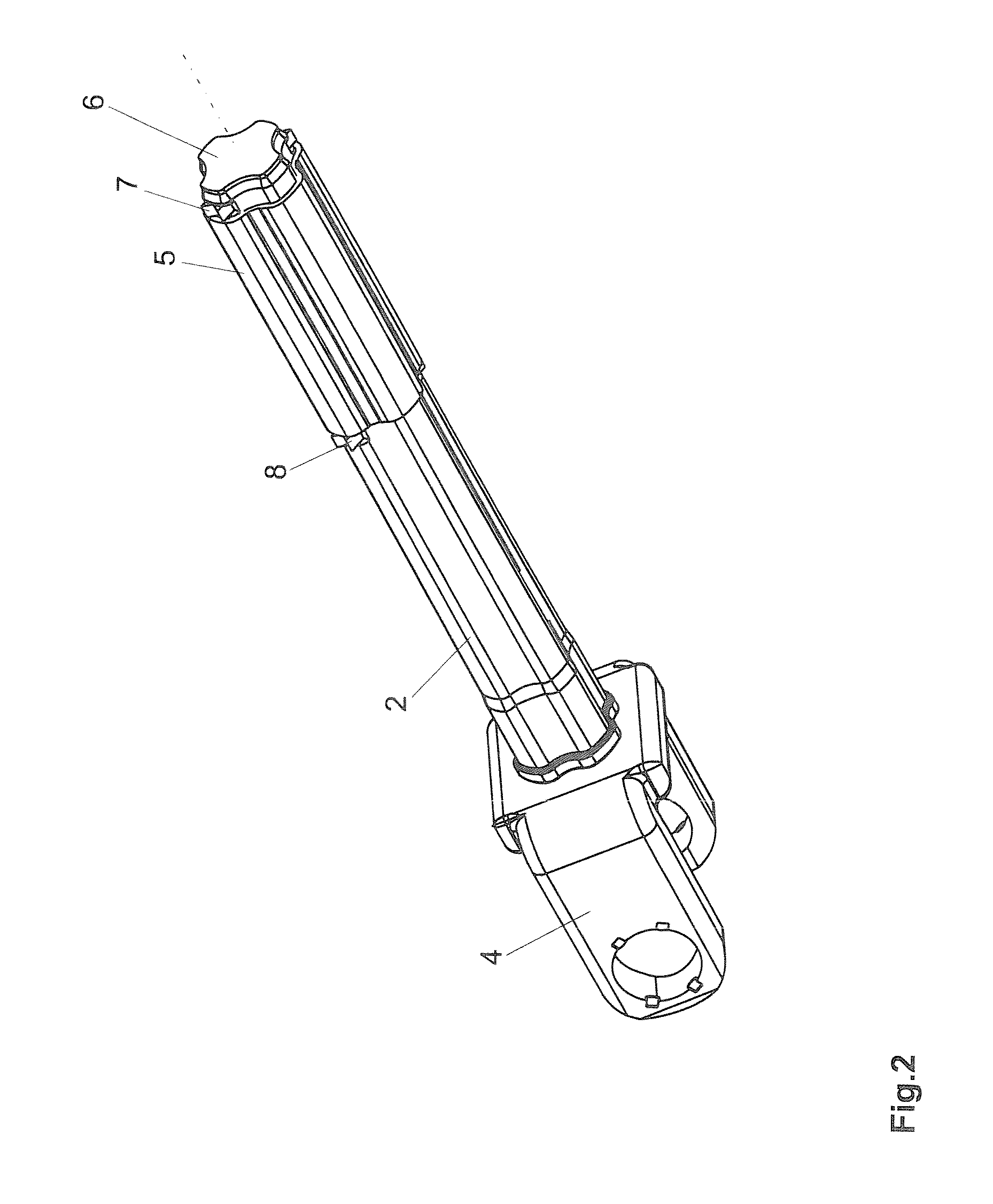
[0032]In FIG. 1 is shown a telescopable steering spindle 1 in a side view. The steering spindle 1 comprises an inner spindle 2 and an outer spindle 3. The inner spindle 2 is provided with a cross section differing from the circular form (=nonround), in this example approximately in the form of a clover leaf. The outer spindle 3 is tubular, with an inner free cross section complementary to the outer circumferential contour of the inner steering spindle. The inner spindle 2 and the outer spindle 3 bear at their end sides connection pieces 4 known per se AS Cardan or universal joints to connect to a steering gear and a steering column. The joint in the example is depicted as a universal joint in which in the connection pieces 4, realized as yokes, the pins of a spider or cross-piece (=cross pin) are rotatably supported, wherein the bearings of the yokes are orthogonally offset with respect to one another. However, it is conceivable and feasible to connect other joints or also entirely ...


PUM


Abstract

An antifriction bushing is provided for the bearing of a telescopable steering spindle having an inner spindle and an outer spindle which are disposed coaxially with respect to one another and displaceably with respect to one another and for the torque transmission have a cross section differing from circular. Between the outer spindle and the inner spindle, an interspace is provided for receiving the antifriction bushing consisting of a thermoplastic synthetic material or comprising such material. The bushing includes an inner surface and an outer surface, and consists of a mixture comprising the material PEEK and additionally at least one of the materials PTFE at a volume fraction of up to maximally 15% and / or graphite at a volume fraction of up to maximally 15% and / or carbon fibers at a volume fraction of up to maximally 40%.

Description

BACKGROUND OF THE INVENTION[0001]a) Field of the Invention[0002]The present invention relates to an antifriction bushing for the bearing of a telescopable steering spindle with an inner spindle and an outer spindle which are disposed coaxially and displaceably with respect to one another and, for torque transmission, have a cross section differing from circular. Between the outer spindle and the inner spindle an interspace is provided for receiving the antifriction bushing consisting of a thermoplastic synthetic material or comprising such, and the bushing has an inner surface and an outer surface. The invention furthermore relates to a telescopable steering spindle with an inner spindle and an outer spindle, which are coaxial with respect to one another and (for the torque transmission) have a cross section differing from circular. Between the outer spindle and the inner spindle an interspace is provided in which such an antifriction bushing is disposed.[0003]b) Description of Rela...

Claims


Application Information

Patent Timeline
IPC IPC(8): F16C3/035F16D3/06F16C29/02F16C33/04
CPCF16D3/06F16D2300/10F16C33/201F16C29/02F16C3/03
Inventor ELTNER, FRANK
Owner THYSSENKRUPP PRESTA AG
Learn More