
Use of refrigeration loops to chill inlet air to gas turbine

a technology of gas turbine and refrigeration loop, which is applied in the direction of domestic cooling equipment, lighting and heating equipment, applications, etc., can solve the problems of gas turbine output power degradation and further pose serious problems, and achieve the effect of reducing the temperature of inlet air

Inactive Publication Date: 2012-07-05
CHEVROU USA INC
View PDF1 Cites 9 Cited by
  • Summary
  • Abstract
  • Description
  • Claims
  • Application Information

AI Technical Summary

Benefits of technology

[0007]As described herein, a method and system for maximizing gas turbine output for a refrigeration loop are provided. The method and system provide a gain in energy efficiency of the gas turbine while compensating for an amount of energy required for consuming a portion of refrigerant.
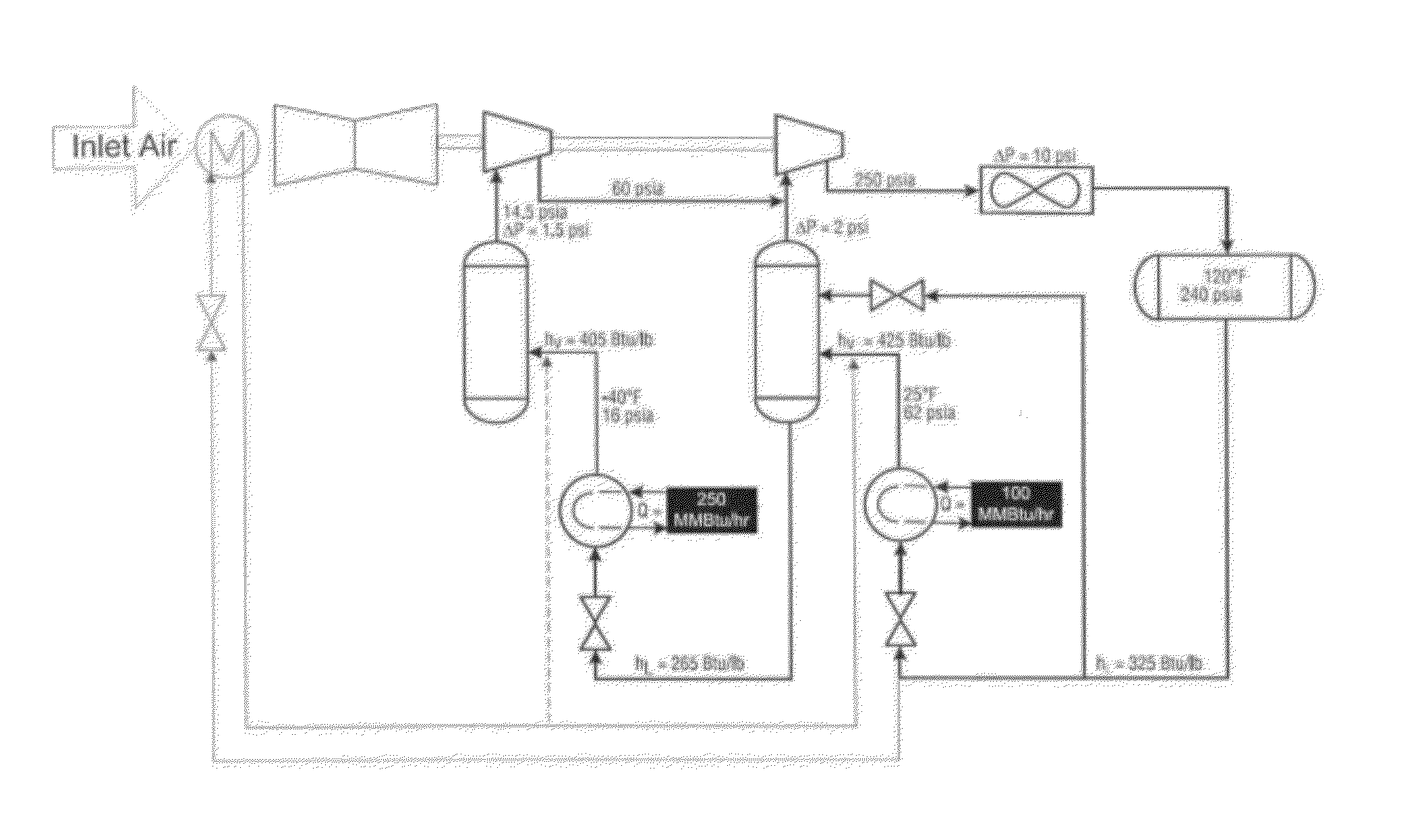
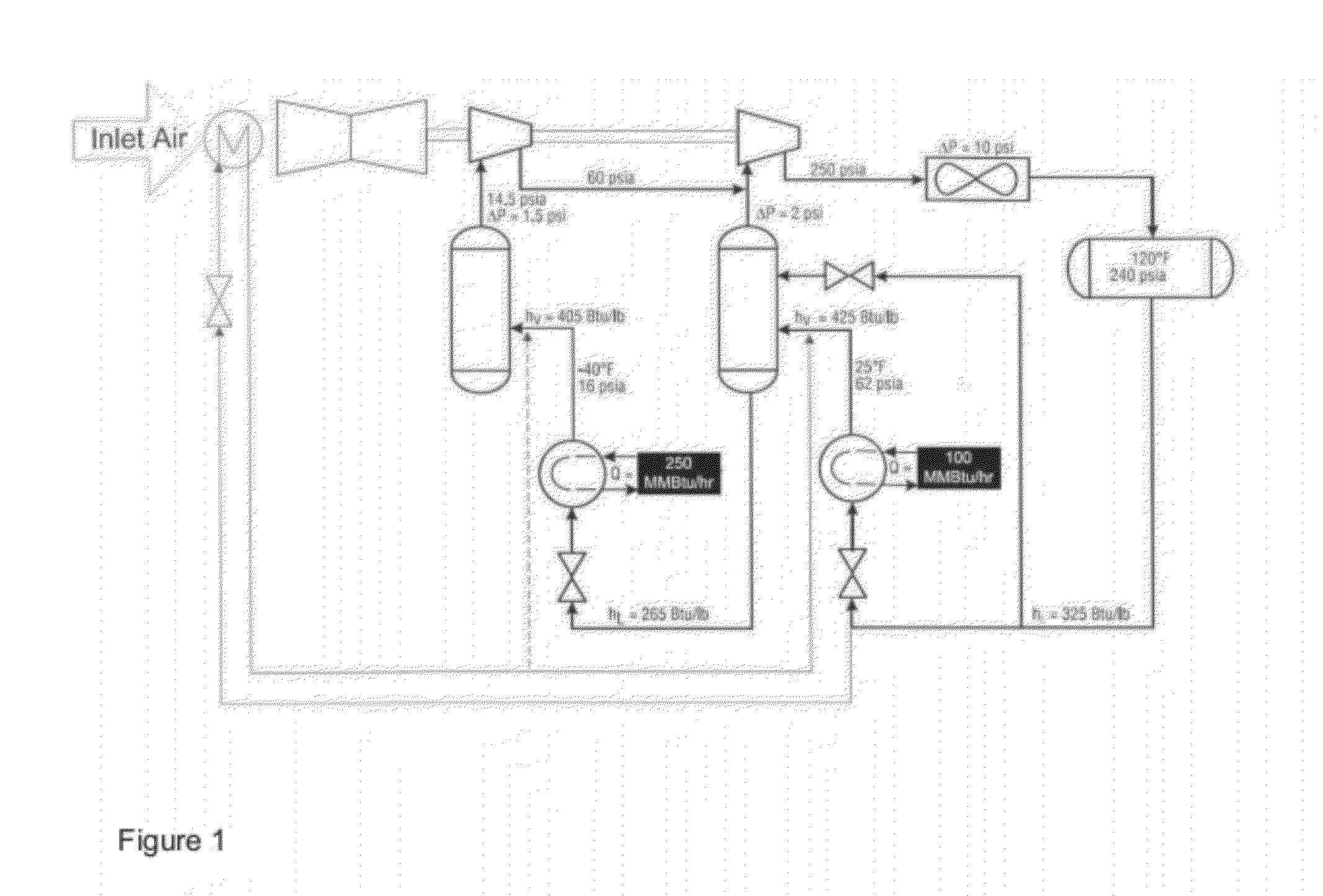
[0008]In one embodiment disclosed herein is an integrated system for refrigeration. The system comprises (a) a refrigeration system comprising a refrigeration loop for air-chilling; (b) a gas turbine for driving a compressor for the refrigeration system; (c) a heat exchanger for consuming a portion of refrigerant from the refrigeration system and cooling a heat transfer fluid; and (d) a second heat exchanger for reducing the temperature of inlet air entering the gas turbine with the heat transfer fluid.
[0009]In another embodiment disclosed herein is an integrated method of maximizing gas turbine output for a refrigeration loop. The method comprises (a) operating a refrigeration loop for chilling processes; (b) operating a gas turbine to drive a compressor for a the refrigeration loop; (c) gasifying a portion of refrigerant from the refrigeration system; and (d) reducing the temperature of inlet air entering the gas turbines by exchanging heat with the gasified portion of refrigerant either directly or indirectly.
[0010]In an additional embodiment disclosed herein is an integrated method of operating a gas turbine used in a refrigeration loop. The method comprises (a) operating a gas turbine to drive a compressor for a refrigeration system comprising a refrigeration loop and (b) chilling inlet air entering the gas turbine by (i) exchanging heat with a refrigerant in the refrigeration loop; or (ii) cooling a heat transfer fluid with a refrigerant in the refrigeration loop, and chilling inlet air entering the gas turbine by exchanging heat with the heat transfer fluid; or both (i) and (ii). In the method the refrigerant in the refrigeration loop comprises methane, ethane, propane, ammonia, a hydrofluorocarbon, a chlorofluorocarbon, a hydrochlorofluorocarbon, a bromofluorocarbon, a bromochlorofluorocarbon, or any combination thereof; and the heat transfer fluid comprises methanol, ethanol, a glycol and water mixture, or any combination thereof. In this method the gas turbine and refrigeration system can be used to produce LNG and the method further comprises cooling and condensing a natural gas stream by reducing the temperature of the natural gas using the refrigeration system.
[0012]In a further embodiment discloses herein is an integrated method for operating a liquefied natural gas (LNG) plant, the method comprising: (i) cooling and condensing a natural gas stream in a refrigeration system to produce liquefied natural gas (LNG); (ii) operating a gas turbine to drive a compressor for the refrigeration system; (iii) regasifying a portion of the LNG; (iv) consuming a portion of the refrigerant from the refrigeration system; and (iv) reducing the temperature of inlet air entering the gas turbine by exchanging heat with the regasified portion of the LNG and with the consumed portion of the refrigerant directly or indirectly.

Problems solved by technology

Degradation of gas turbine output power with a rise in ambient air temperature further poses a serious problem.

Method used


Image

  • Use of refrigeration loops to chill inlet air to gas turbine
  • Use of refrigeration loops to chill inlet air to gas turbine
  • Use of refrigeration loops to chill inlet air to gas turbine

Examples


Embodiment Construction

[0015]In the present methods and systems, a portion of refrigerant from the refrigeration system is utilized to cool the inlet air to the gas turbines in the refrigeration system, either directly or indirectly.

DEFINITIONS

[0016]In accordance with this detailed description, the following abbreviations and definitions apply. It must be noted that as used herein, the singular forms “a”, “an”, and “the” include plural referents unless the context clearly dictates otherwise. Thus, for example, reference to “gas turbine” includes a plurality of such.

[0017]Unless otherwise stated, the following terms used in the specification and claims have the meanings given below:

[0018]“LNG” is liquefied natural gas. Natural gas from the well can consist of various hydrocarbons and contaminants; natural gas for the domestic market is comprised primarily of methane. At ambient temperature and pressure, LNG exists as a gas, but it can be cooled and / or pressurized to provide a liquid, which facilitates stor...


PUM


Abstract

As described herein, a method and system for operating a refrigeration system are provided. In the present methods and systems, a portion of the refrigerant from the refrigeration system is used for reducing the temperature of inlet air entering the gas turbine. The refrigeration system disclosed herein can be used for LNG production, air separation, food storage, or ice-making.

Description

[0001]This application is co-pending to U.S. patent application entitled “Method to Maximize LNG Plant Capacity in All Seasons”, filed 30 Dec. 2010, Attorney Docket No. 70205.0221US01, the contents of which are herein incorporated by reference in their entirety.FIELD OF THE INVENTION[0002]The present application relates to a method and system which maximizes gas turbine output for a refrigerant loop. The method consumes a small amount of refrigerant and utilizes the refrigeration to chill the inlet air to the gas turbine (GT) machines used in the refrigeration system. This approach enhances the gas turbine power output and efficiency which, in turn, increases the production of the plant. The gain in efficiency in production can compensate for the consumption of refrigerant.BACKGROUND OF THE INVENTION[0003]Gas turbines are commonly used for driving compressors in refrigeration systems. For example, gas turbines are used in to drive refrigeration compressors in LNG production, air sep...

Claims


Application Information

Patent Timeline
Patent Type & Authority Applications(United States)
IPC IPC(8): F25J1/02F25D17/04F25C1/00F25B1/00F25J3/08
CPCF01D15/005F02C7/143F25B27/00F25J1/0022F25J1/0082F25J1/0283F25J1/0087F25J1/0092F25J1/0097F25J1/0236F25J1/0085F02C7/141F25B49/00
Inventor HUANG, STANLEY H.HAVLIK, ROBERT C.
Owner CHEVROU USA INC
Learn More