

Wind turbine rotor blade
- Summary
- Abstract
- Description
- Claims
- Application Information
AI Technical Summary
Benefits of technology
Problems solved by technology
Method used
Image

Examples
first embodiment
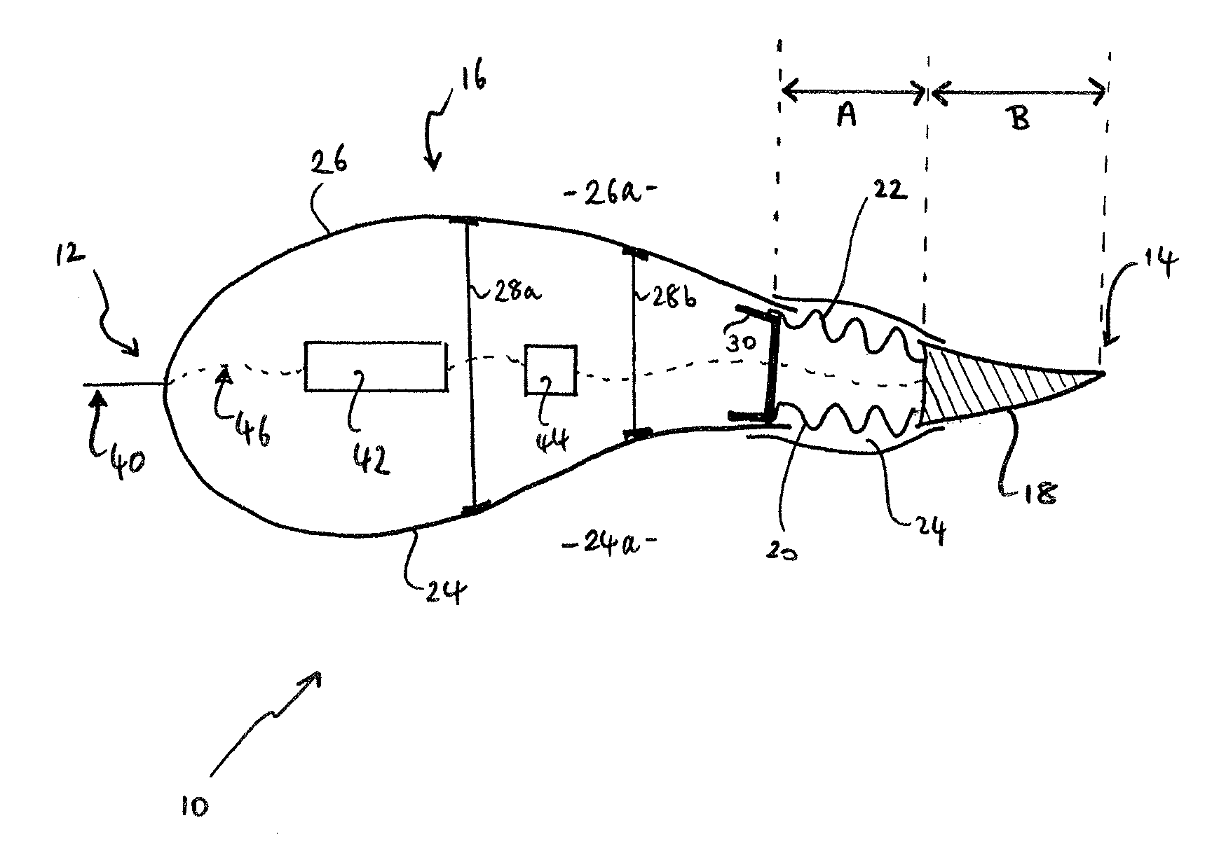
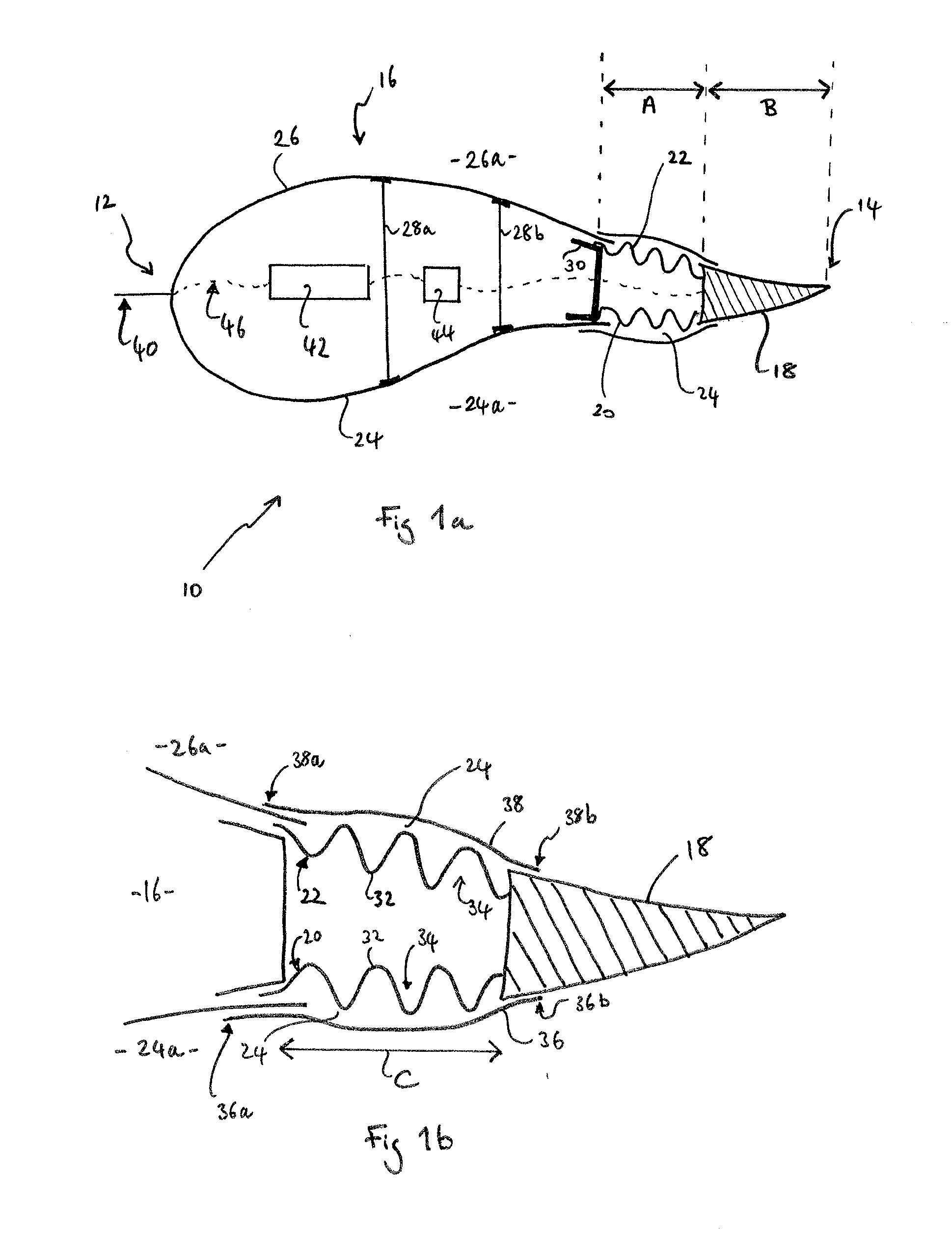
[0050]FIG. 1a shows an aerodynamic airfoil cross-section of a wind turbine blade in accordance with the present invention. The blade section 10 extends in a chordwise direction from a leading edge 12 to a trailing edge 14, and has a camber in the chordwise direction. The leading edge 12 is defined by a blade body 16, and the trailing edge 14 is defined by a trailing edge flap 18. The trailing edge flap 18 is attached to the blade body 16 via first and second deformable panels 20, 22 in a junction region 24 of the blade 10. The deformable panels 20, 22 each have a chord length of approximately 10% of the chord length of the blade (as shown by arrow A) whilst the trailing edge flap 18 has a chord length of approximately 20% of the chord length of the blade 10 (arrow B).
[0051]The blade body 16 is manufactured from first and second half shells 24, 26 of E-glass fibre reinforced epoxy resin (E-GFRP), which are joined together substantially at the leading edge 12 of the blade 10. The firs...
second embodiment
[0062]FIG. 4 shows a trailing edge flap 50 of a wind turbine blade in accordance with the present invention. In this example, the trailing edge flap 50 is attached to a blade body 52 via a corrugated panel 54 on a suction side 56 of the blade at a junction region 58 between the blade body 52 and the trailing edge flap 50.
[0063]In contrast to the first embodiment, there is no corrugated panel on a pressure side 60 of the blade. Instead, the skin 62 on the pressure side 60 is broken at the junction region 58. A longitudinal gap 64 is defined in the pressure side 60 of a C-shaped web 66 between the blade body 52 and the trailing edge flap 50. An end portion 68 of the skin 62 on the pressure side 60 of the trailing edge flap 50 extends through the gap 64 into an internal region 70 of the blade body 52. This arrangement provides a sliding joint between the trailing edge flap 50 and the blade body 66 on the pressure side 60 of the blade.
[0064]The solid line in FIG. 4 represents the traili...
PUM
 Abstract
Description
Claims
Application Information