Hysteretic CL power converter

a power converter and hysteretic cl technology, applied in the direction of electric variable regulation, process and machine control, instruments, etc., can solve the problems of slow overall response rhpz can complicate the stability of the loop, and difficult to obtain fast control of the boost converter, etc., to reduce the value, size and cost of the passive components.

Active Publication Date: 2012-07-05
QUALCOMM INC
View PDF13 Cites 119 Cited by
  • Summary
  • Abstract
  • Description
  • Claims
  • Application Information

AI Technical Summary

Benefits of technology

[0021]It is an objective of the present invention to provide an inductive boost switching power converter that can ope

Problems solved by technology

Fast control of boost converters is difficult to obtain in CCM because there is always an intrinsic delay in providing energy to the load since the inductor has to be first charged with current flowing in it.
This RHPZ can complicate the stability of the loop and generally is dealt with by rolling off the loop gain of the switching voltage regulator at relatively low frequency, making the overall response of the boost converter quite slow.
However, as mentioned, these types of control methods do not present high bandwidth and require the adoption of la

Method used


Image

  • Hysteretic CL power converter
  • Hysteretic CL power converter
  • Hysteretic CL power converter

Examples


Embodiment Construction

A FIG. 4

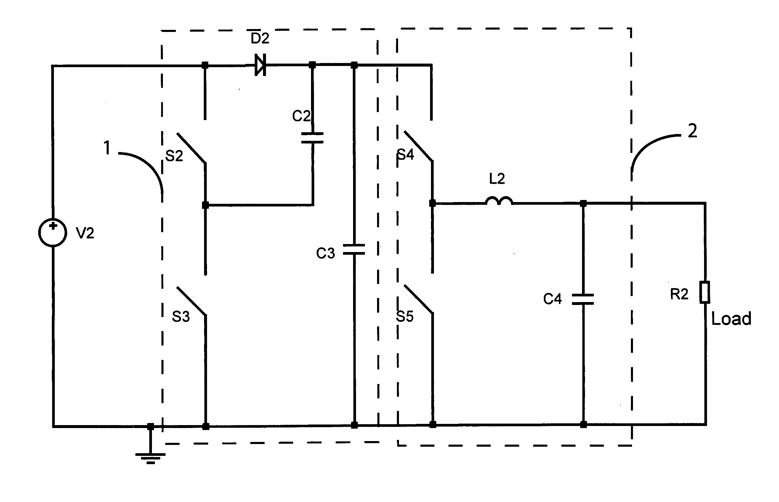
[0059]FIG. 4 is showing the first general embodiment of the invention. In particular FIG. 4 shows the schematic of the block diagram of the pseudo-hysteretic switching boost converter. FIG. 4 describes a novel approach in which a capacitive charge pump circuit boosts the voltage to a value higher than the desired output voltage and a successive inductive step down converter regulates the voltage to the desired value with high efficiency. However in FIG. 4 some of the components of the two mentioned blocks are merged or eliminated to form a novel circuit topology.

[0060]The circuit has two nodes, (8 and 9) that are switching. In particular the node 9 is toggled between the input voltage V2 and ground. The node 8 is switching between the input voltage V2 and potentially approximately 2 (two) times V2. Therefore appropriate modulation of the duty cycle can result in a regulated output voltage of the converter with any value between the input voltage and twice the input voltage.

[...


PUM


Abstract

A novel switching hysteretic power converter is presented. The power converter combines the function of a capacitive charge pump with the function of an inductive step down converter to obtain a switching boost converter with a much simpler control method with respect to conventional inductive boost power converters. The hysteretic control provides stable operation in all conditions with excellent load transient response. Furthermore the hysteretic control allows high frequency switching reducing the size and cost of the passive components. The Discontinuous Conduction Mode of operation provides very high efficiency even at light loads. The presented power converter can be operated as a boost converter or as a buck converter simply by changing the switching phase of one switch. In both types of operation the efficiency of the hysteretic power converter can be quite high even at high switching frequencies.

Description

BACKGROUND OF THE INVENTION[0001]1. Field of the Invention[0002]The present invention is in the field of power converters. The present invention is further in the field of semiconductor switching power converters. The present invention further relates to the field of integrated hysteretic non isolated control methods for switching power converters and circuits. The implementation is not limited to a specific technology, and applies to either the invention as an individual component or to inclusion of the present invention within larger systems which may be combined into larger integrated circuits.[0003]2. Brief Description of Related Art[0004]Modern electronic applications require power management devices that supply power to integrated circuits or more generally to complex loads. In general power switching converters are becoming more and more important for their compact size, cost and efficiency. The switching power converters comprise isolated and non isolated topologies. The gal...

Claims


Application Information

Patent Timeline
IPC IPC(8): H02M3/18
CPCH02M3/07Y02B70/1466H02M2001/007H02M3/1588H02M1/007Y02B70/10
Inventor MENEGOLI, PAOLOMARINO, FABIO ALESSIO
Owner QUALCOMM INC
Why Eureka
Try Eureka