
Low pressure device for melting and purifying silicon and melting/purifying/solidifying method

a technology of low pressure device and silicon feedstock, which is applied in the direction of lighting and heating apparatus, charge manipulation, furnaces, etc., can solve the problems of affecting the electric performance of silicon, unable to meet the requirements for photovoltaic or microelectronic use, and relatively cheap silicon of metallurgical silicon, etc., to achieve fast and efficient elimination of dopants and metallic impurities, and easy implementation

Inactive Publication Date: 2012-07-12
APOLLON SOLAR SAS
View PDF0 Cites 3 Cited by
  • Summary
  • Abstract
  • Description
  • Claims
  • Application Information

AI Technical Summary

Benefits of technology

[0015]The object of the invention is to provide a silicon purification device that is easy to implement and that performs fast and efficient elimination of the dopants and metallic impurities present in a metallurgical silicon feedstock.

Problems solved by technology

Metallurgical silicon is a relatively cheap silicon that, in this form, is unable to satisfy the criteria necessary for use in the photovoltaic field or in the microelectronics field.
Metallurgical silicon does in fact contain too high concentrations of impurities, for example of metallic elements such as iron, aluminium, copper or titanium, which greatly impair the electric performances of the silicon (in particular in terms of feedstock carrier diffusion length).
However, these purification steps have the effect of very greatly increasing the cost of silicon which is linked to the final cost of photovoltaic panels.
A silicon purification channel by a gaseous method also exists which is also expensive to implement.
Purification by solidification is however only efficient if the impurity presents a small segregation coefficient between liquid phase and solid phase, i.e. a low ratio between the concentration in solid phase compared with the concentration in liquid phase.
If the segregation coefficient is close to one, the concentration in liquid phase is slightly higher than that in solid phase, which limits the efficiency of purification by segregation.
Typically, the segregation coefficient is equal to 0.8 for boron which makes this technique unsuitable for greatly reducing the boron concentration.
This melting / purification device is therefore particularly space consuming as it uses four different and specific crucibles at each step.
It is also time consuming, energy consuming and costly as the method is divided into four specific steps which makes it fairly impractical to use.

Method used


Image

  • Low pressure device for melting and purifying silicon and melting/purifying/solidifying method
  • Low pressure device for melting and purifying silicon and melting/purifying/solidifying method
  • Low pressure device for melting and purifying silicon and melting/purifying/solidifying method

Examples


Embodiment Construction

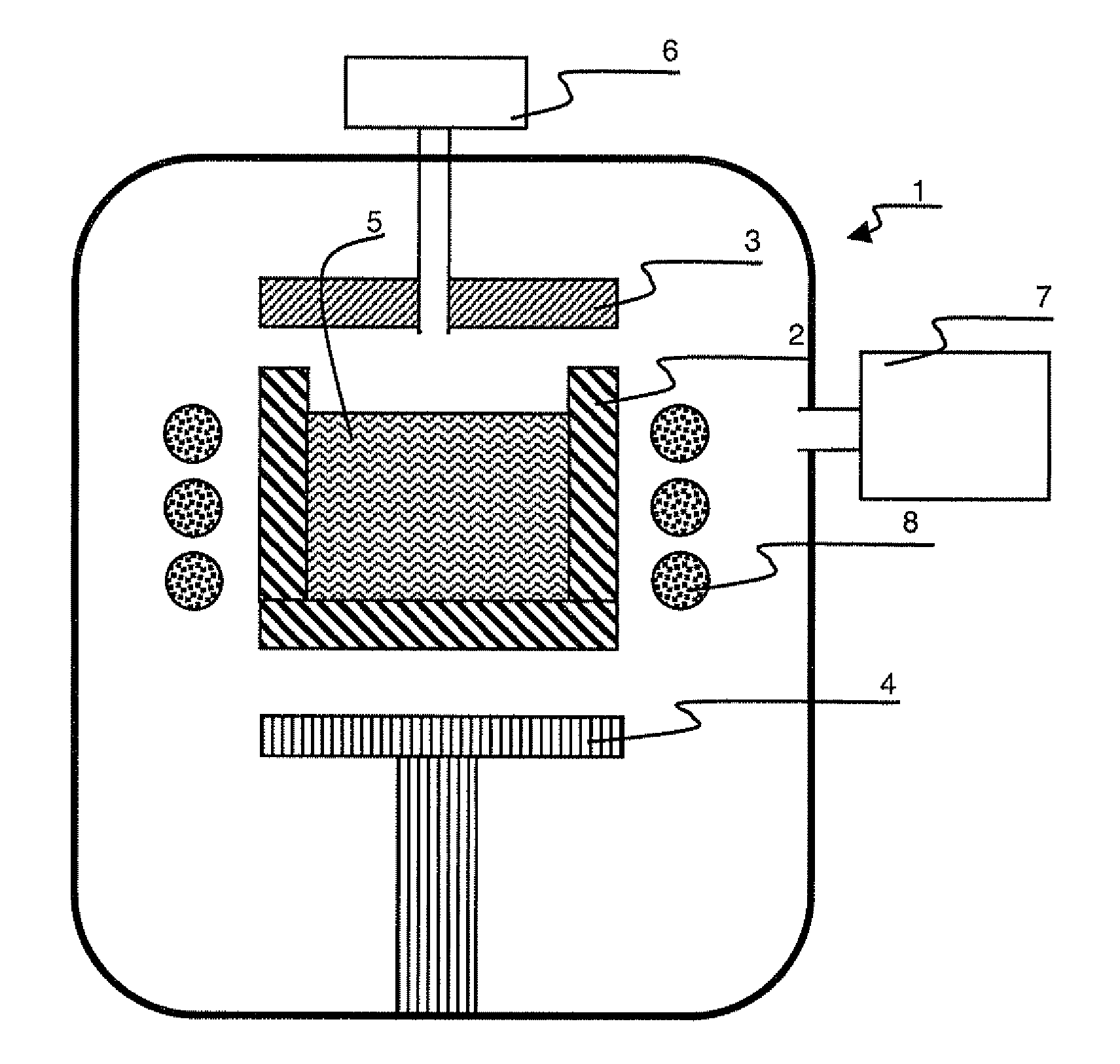
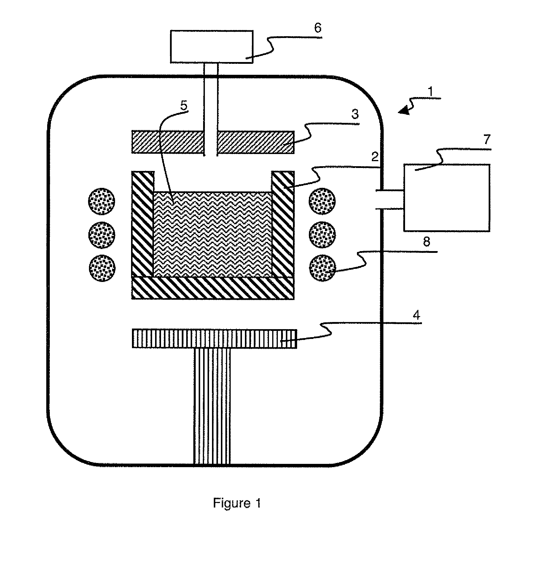
[0026]The melting / purifying device comprises a sealed chamber 1 inside which a crucible 2 is arranged. Crucible 2 is arranged between a heating device 3 and a heat exchanger 4. Heating device 3 and heat exchanger 4 define a thermal gradient in crucible 2 and therefore in a silicon feedstock 5 placed inside the crucible. Feedstock 5 can also be formed by a silicon alloy, for example silicon-germanium alloys, but it contains a majority of silicon.

[0027]Crucible 2 is for example made from graphite, quartz, or silica. Crucible 2 can be protected by an internal deposition which forms a protective layer and / or a non-adhesive layer (not shown). This internal deposition can be formed by a layer of silicon nitride, silicon dioxide, silicon oxynitride, a stack of the latter. Crucible 2 is advantageously a reusable crucible.

[0028]Heating device 3 is for example a resistive heating device, typically a heated susceptor. It can also be envisaged to have heating of the feedstock by means of an ind...


PUM

PropertyMeasurementUnit
Pressureaaaaaaaaaa
Pressureaaaaaaaaaa
Pressureaaaaaaaaaa

Abstract

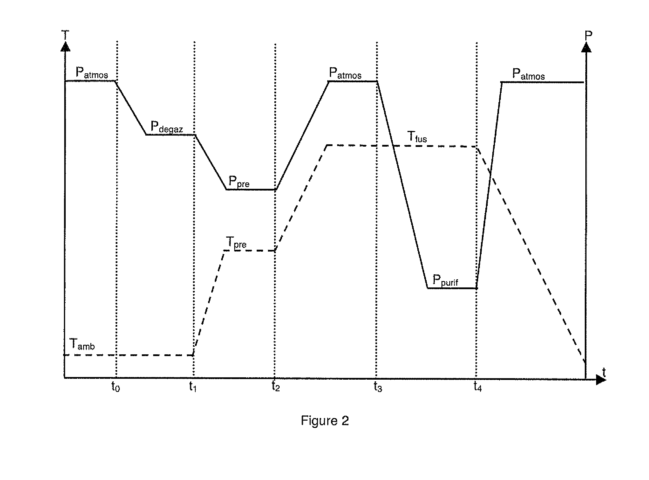
The device for melting and purifying of a silicon feedstock comprises a crucible arranged inside a sealed chamber. A thermal gradient can be applied to the crucible by an arranged heat exchanger and a heating device. The device likewise comprises a device for reducing the pressure inside the chamber to a value lower than 10−2 mbar and a device for stirring the silicon in the crucible. The silicon feedstock successively undergoes degassing and pre-heating to atmospheric temperature, and then melting and low pressure, high temperature purification. Once the low-pressure purification step has been completed, directed crystallization is carried out.

Description

BACKGROUND OF THE INVENTION[0001]The invention relates to a device for melting and purifying a silicon feedstock comprising:[0002]a chamber,[0003]a crucible arranged inside the chamber,[0004]a heat exchanger arranged inside the chamber,[0005]a heating device of the silicon feedstock inside the chamber,[0006]an stirring device of the silicon in the crucible.[0007]The invention also relates to a melting / purifying / solidifying method of a silicon feedstock of metallurgical origin.STATE OF THE ART[0008]Metallurgical silicon is a relatively cheap silicon that, in this form, is unable to satisfy the criteria necessary for use in the photovoltaic field or in the microelectronics field. Metallurgical silicon does in fact contain too high concentrations of impurities, for example of metallic elements such as iron, aluminium, copper or titanium, which greatly impair the electric performances of the silicon (in particular in terms of feedstock carrier diffusion length). Metallurgical silicon al...

Claims


Application Information

Patent Timeline
IPC IPC(8): F27B14/00F27D3/00
CPCB01J6/007C30B29/06C30B11/007C01B33/037
Inventor KRAIEM, JEDEINHAUS, ROLANDLAUVRAY, HUBERT
Owner APOLLON SOLAR SAS
Learn More