Control device for turbocharged engine

a control device and turbocharger technology, applied in the direction of electrical control, process and machine control, instruments, etc., can solve the problems of excessive rise in the revolution speed of the turbine constituting the turbocharger, damage to the turbocharger, and increase in the revolution speed

Inactive Publication Date: 2012-07-12
MITSUBISHI HEAVY IND LTD
View PDF36 Cites 18 Cited by
  • Summary
  • Abstract
  • Description
  • Claims
  • Application Information

AI Technical Summary

Benefits of technology

[0015]Therefore, the turbine revolution speed can be estimated from the operating state of the engine, without adding components that directly detect the turbine revolution speed. As a consequence, the occurrence of problems associated with the increase in the product cost resulting from the installation of a sensor for detecting the turbine revolution speed and the decrease in product reliability caused by failures and erroneous detection of the sensor can be avoided.
[0030]The present invention can provide a control device for a turbocharged engine which is capable of accurately estimating the revolution speed of a turbine, without using additional components for directly detecting the turbine revolution speed, and of accurately keeping the turbine revolution speed at the allowed value or below and preventing excessive rotation by accurately estimating the turbine revolution speed.

Problems solved by technology

Therefore, when the turbocharged engine is used at a high altitude where the air density is low, the revolution speed of the turbine constituting the turbocharger can rise excessively to supply such a large amount of air to the engine and such increase in revolution speed can damage the turbocharger.
Therefore, the supercharging pressure during the operation is comparatively high and the problem associated with black fume generation is unlikely to be encountered even when the exhaust gas is recirculated at a high altitude where the air density is low.
Since it is usually not necessary to control the revolution speed of the turbocharger, when the technique disclosed in Patent Document 1 is used, the revolution speed sensor is provided only for detecting the excessive revolution of the turbine which results in undesirable increase of the product cost.
Since the volume flow rate changes depending on atmospheric pressure, the calculation of volume flow rate cannot be said to be performed accurately.
Therefore, the control cannot be said to be performed accurately.
In the technique disclosed in Patent Document 2, the turbine revolution speed is decreased by opening the EGR control valve, but in a high-load operation, the air excess ratio is inherently low and therefore smoke easily appears and the valve opening operation performed under a low atmospheric pressure at which the turbine revolution speed increases leads to generation of a large amount of smoke.
Further, in applications other than those to construction machines, namely such that the operation state changes from a low-load state to a high-load state, where the EGR is introduced to protect against excessive rotation of the turbocharger, this is highly probable to cause the problem associated with black smoke generation.
Therefore, applications other than those to construction machines are difficult and the application range is narrow.
When the intake temperature is not taken into account, as in the technique disclosed in Patent Document 2, the parameters should be set such that no excessive rotation occurs even under conditions with a high intake temperature at which the excessive rotation of the turbine easily occurs, and when the intake temperature is low, the fuel injection amount is unnecessarily restricted and the engine output is also unnecessarily restricted.

Method used


Image

  • Control device for turbocharged engine
  • Control device for turbocharged engine
  • Control device for turbocharged engine

Examples


embodiment 1

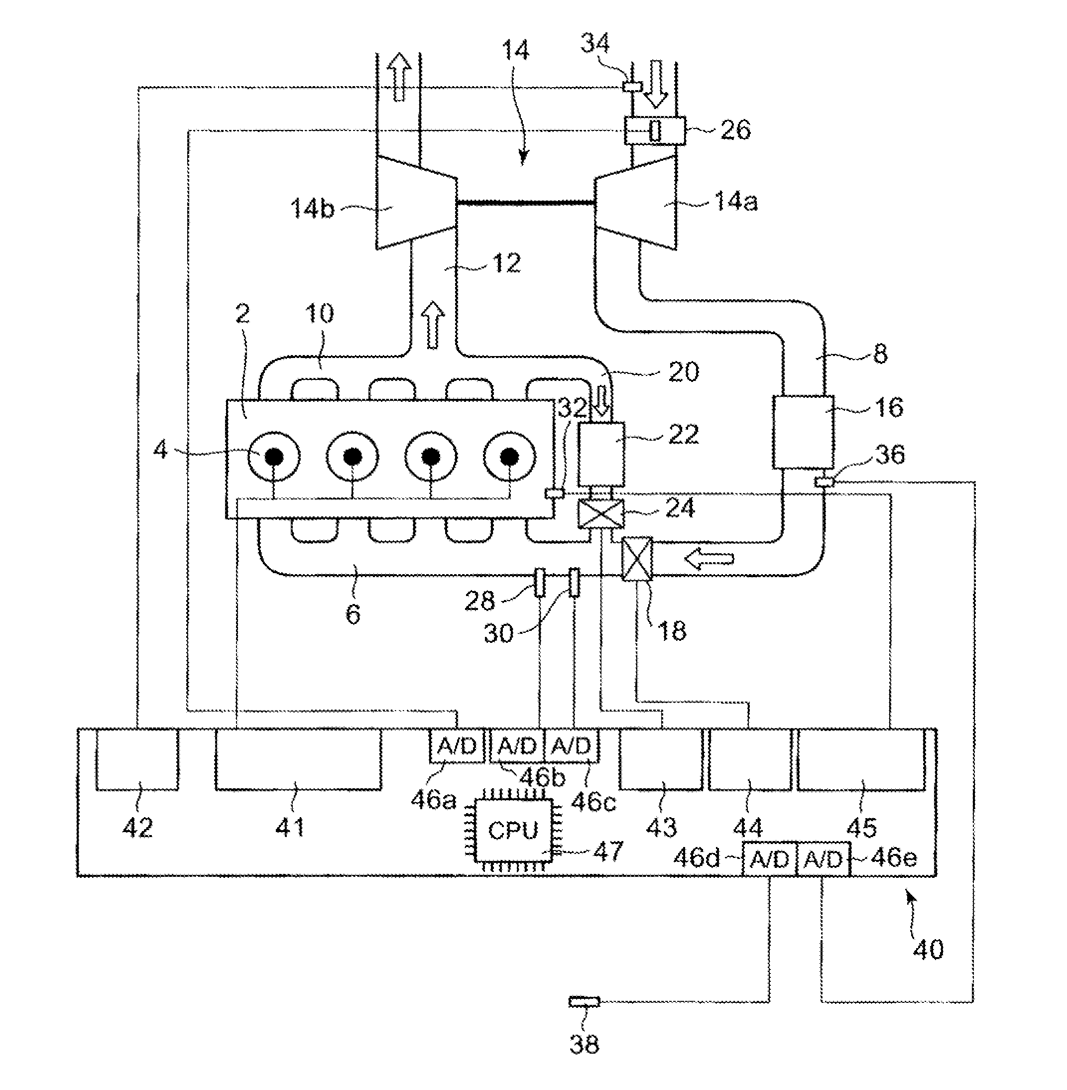
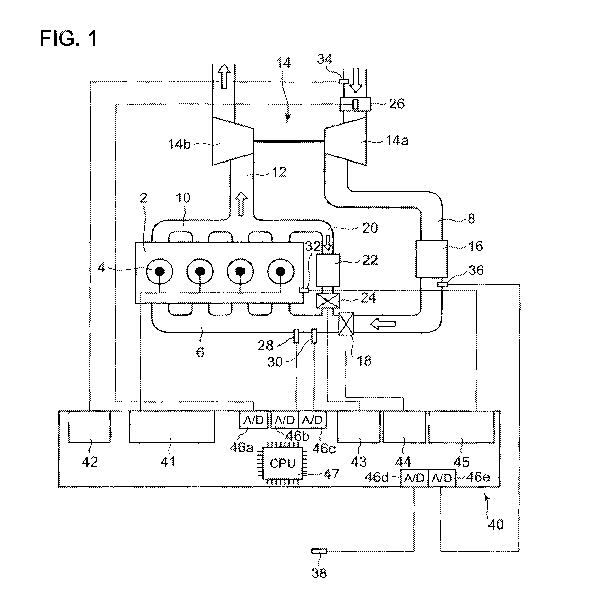
[0045]FIG. 1 is a schematic diagram illustrating engine surroundings where the control device for a turbocharged engine according to Embodiment 1 is used. In FIG. 1, an engine 2 is a four-cycle diesel engine having four cylinders.

[0046]In the engine 2, intake passages 8 merge via an air supply manifold 6, and an exhaust passage 12 is connected to the engine by an exhaust manifold 10.

[0047]A compressor 14a of a turbocharger 14 is provided in the intake passage 8. The compressor 14a is driven coaxially with the below-described turbine 14b. An intercooler 16 performing heat exchange between the atmosphere and the supplied air flowing through the intake passage 8 is provided downstream of the compressor 14a in the intake passage 8. A throttle valve 18 that adjusts the flow rate of supplied air flowing through inside the intake passage 8 is provided downstream of the intercooler 16 in the intake passage 8.

[0048]An air flowmeter 26 that detects an intake flow rate and a temperature sensor...

embodiment 2

[0106]A schematic diagram illustrating the engine surrounding where the control device for a turbocharged engine of Embodiment 1 is used is similar to that shown in FIG. 1, which is explained in Embodiment 1. Therefore, FIG. 1 will be used and the explanation thereof will be omitted.

[0107]FIG. 6 is a drawing illustrating the control logic of fuel injection amount in Embodiment 2.

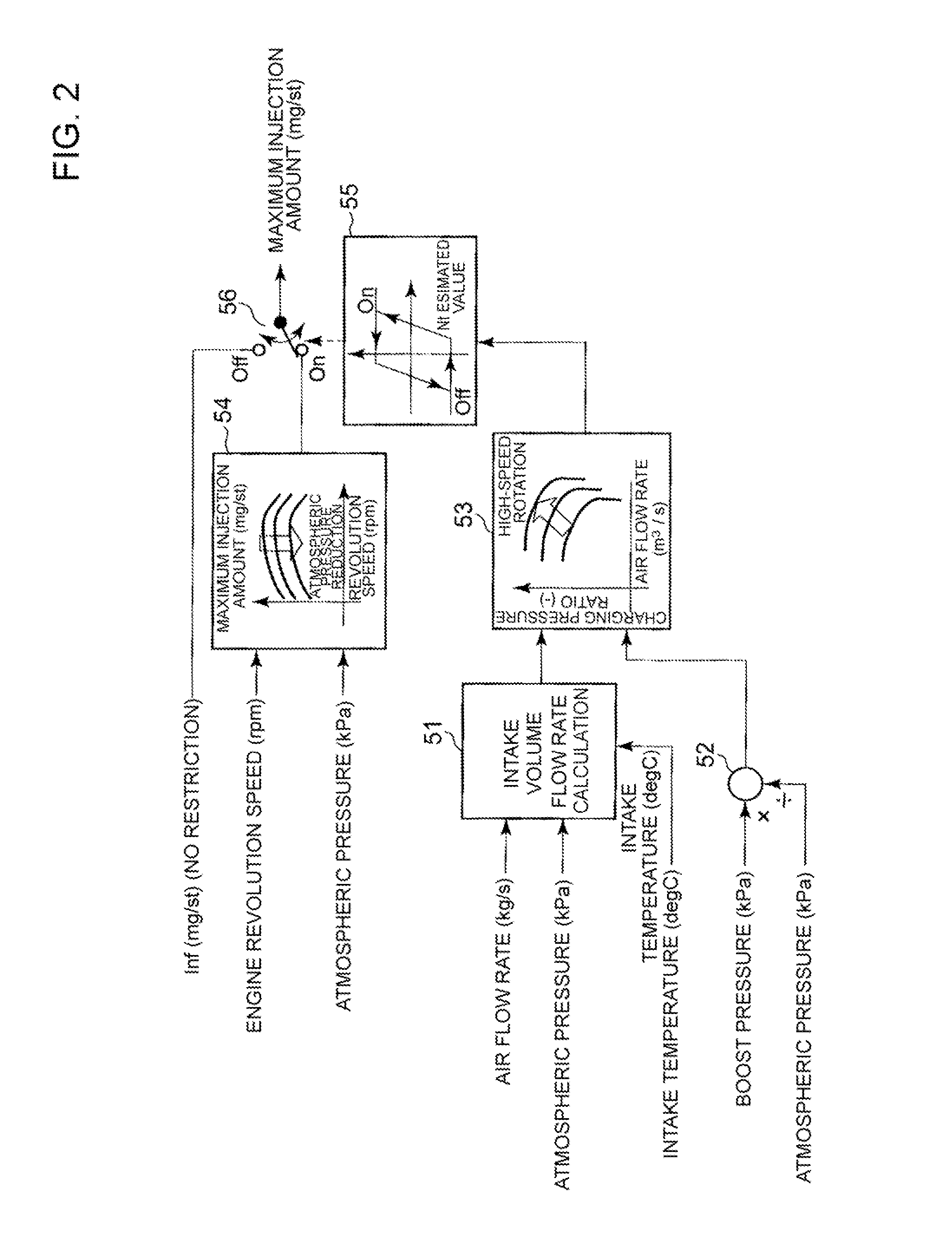
[0108]The reference numerals in FIG. 6 that are identical to those in FIG. 2 denote same operations and control and the explanation thereof is herein omitted.

[0109]In Embodiment 2, a method for estimating the turbine revolution speed is different from that of Embodiment 1.

[0110]The method for estimating the turbine revolution speed in Embodiment 2 will be explained below with reference to FIG. 6.

[0111]In the box represented by the reference numeral 61 in FIG. 6, the ECU 40 inputs the atmospheric pressure (kPa) detected by the pressure sensor 38 and the intake temperature (° C.) detected by the temperature se...

embodiment 3

[0116]FIG. 8 is a drawing illustrating the control logic of fuel injection amount in Embodiment 3.

[0117]The reference numerals in FIG. 8 that are identical to those in FIG. 2 denote same operations and control and the explanation thereof is herein omitted.

[0118]In Embodiment 3, the intake temperature (° C.) estimated from the air supply manifold temperature (° C.) can be used instead of the intake temperature (° C.) used when intake volume flow rate calculation 51 in Embodiment 1 is performed.

[0119]In FIG. 8, the ECU 40 passes the air supply manifold temperature (° C.) detected by the temperature sensor 28 through a low-pass filter 71 and finds the intake temperature (° C.) from the air supply manifold temperature (° C.) by using the map in the box 72. The low-pass filter 71 is used with the object of suppressing the effect of the operation pattern during transient operation on variations in the air supply manifold temperature.

[0120]FIG. 9 is a graph illustrating the relationship be...


PUM


Abstract

An object of the present invention is to provide a control device for a turbocharged engine capable of accurately estimating the revolution speed of a turbine without using additional components for directly detecting the turbine revolution speed, and by accurately estimating the turbine revolution speed, capable of accurately keeping the turbine revolution speed at an allowed value or below and preventing excessive rotation. The control device for a turbocharged engine includes a turbocharger having a compressor disposed in an intake passage of an engine, and a turbine disposed in an exhaust passage of the engine, a fuel injection amount control unit for controlling a fuel injection amount to the engine according to an operating state of the engine, and a turbine revolution speed estimation unit for determining by calculations an estimated value of a revolution speed of the turbine from the operating state of the engine. When the estimated value of the turbine revolution speed exceeds a predetermined allowed value, the fuel injection control unit controls the fuel injection amount such that the estimated value of the turbine revolution speed becomes equal to or less than the allowed value.

Description

TECHNICAL FIELD[0001]The present invention relates to a control device for a turbocharged engine, and more particularly to a control device for a turbocharged engine capable of accurately keeping the turbine revolution speed at an allowed value or below.BACKGROUND ART[0002]A large number of vehicles and construction machines have been using turbocharged engines.[0003]When a turbocharged engine is used at a high altitude where the air pressure is low and air density is low, where the amount of air supplied to the engine is to be same as that when the engine is used at a low altitude, it is necessary to supply the larger amount of air than at a low altitude, if this amount is represented by the volume of air supplied to the engine. Therefore, when the turbocharged engine is used at a high altitude where the air density is low, the revolution speed of the turbine constituting the turbocharger can rise excessively to supply such a large amount of air to the engine and such increase in r...

Claims


Application Information

Patent Timeline
Patent Type & Authority Applications(United States)
IPC IPC(8): F02D41/30
CPCF02B2037/122F02B2039/168F02D41/0007F02D41/18Y02T10/144F02D2200/0406F02D2200/0414F02D2200/703F02D41/38Y02T10/12F02B37/12F02B39/16F02D41/04
Inventor IDE, KAZUNARIYAMADA, TOMOHIDE
Owner MITSUBISHI HEAVY IND LTD
Why Eureka
Try Eureka