
Automatic c-arm viewing angles for structural heart disease treatment

a technology of c-arm and heart disease, applied in the field of automatic positioning of xray image acquisition devices, can solve the problems of unnecessary exposure of patients to x-ray radiation, and achieve the effect of reducing the time of x-ray radiation exposure and reducing the exposure of patients' bodies

Active Publication Date: 2012-07-19
KONINKLIJKE PHILIPS ELECTRONICS NV
View PDF1 Cites 7 Cited by
  • Summary
  • Abstract
  • Description
  • Claims
  • Application Information

AI Technical Summary

Benefits of technology

[0010]Furthermore, in adjusting viewing angles of an X-ray image acquisition device a parallax effect may be apparent. A parallax stands for the apparent displacement of an object viewed along two different lines of sight. It may be measured by an angle of inclination between these two lines. Objects situated nearby the viewer or the X-ray source, respectively, develop a larger parallax than more distant objects when they are observed from different positions. In nature, this parallax leads to the ability of humans or animals to determine a distance by viewing an object along two different lines of sight. Generally, since the fluoroscopy images are two-dimensional this parallax effect may influence the image quality regarding imprecise reproduction or representation of object lengths in the live images.
[0013]Furthermore, there may be a need for a method for positioning an X-ray image acquisition device that allows minimizing or completely eliminating the parallax effect of live fluoroscopy images.
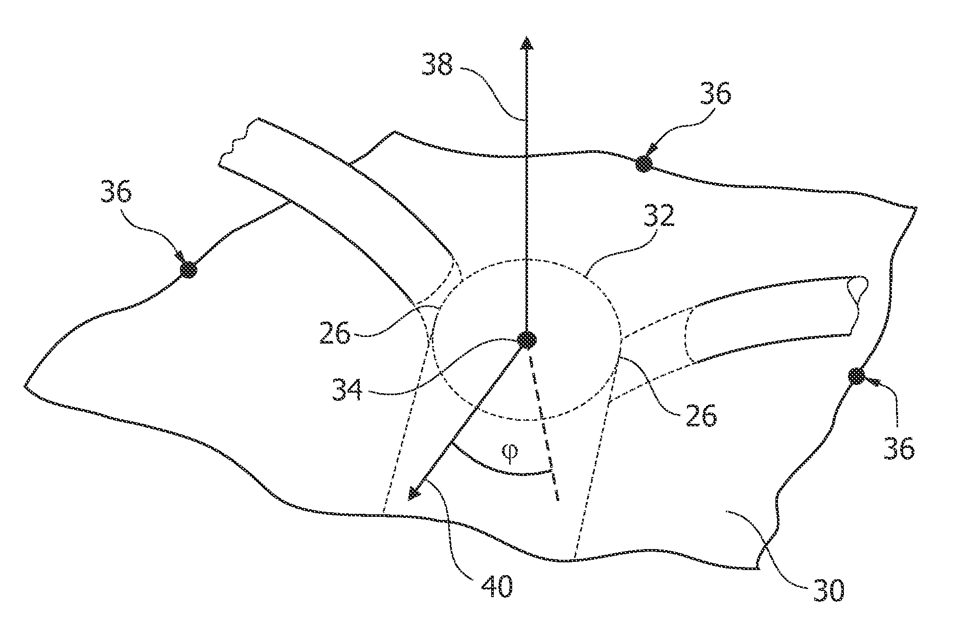
[0020]The advantage of defining the viewing direction relative to a reference plane by tangential vectors as X-ray image acquisition device viewing directions lies in the ability for precise placement of an intracardiac device, which may be realized as an aortic valve stent, inside the pathology location. Consequently, a viewing direction in normal direction, in the range of the normal vector on the reference plane may be useful for placing for example an atrial septal defect closure device or similar.
[0027]By conducting a method according to the present invention comprising the above identified aspects several advantages may be achieved. A misplacement of a percutaneous device or other medical instruments can be prevented. By planning optimal viewing directions prior to the intervention an optimal viewing direction for the whole intervention procedure may be achieved. It should therefore be considered impossible to conduct the intervention with a sub-optimal viewing direction in which the surgeon may have a wrong assumption of the correct treatment, correct deployment of intracardiac devices or the such. Therefore, the method according to the present invention provides a clear improvement for interventional treatments.
[0028]Furthermore, conducting the method according to the present invention provides in a reduction of exposure of the patient's body to X-ray radiation. It may be unnecessary to adjust the X-ray image acquisition device several times during the interventional treatment where the live fluoroscopy images are not used for guiding the medical instruments. By the method according to the present invention an automatic adjustment of the X-ray image acquisition device provides for an optimal viewing direction at all times. Thereby, the intervention process is accelerated and thus the time of X-ray radiation exposure is reduced.

Problems solved by technology

Also, adjusting the viewing direction during the intervention leads to an unnecessary exposure of the patient to X-ray radiation.

Method used


Image

  • Automatic c-arm viewing angles for structural heart disease treatment
  • Automatic c-arm viewing angles for structural heart disease treatment
  • Automatic c-arm viewing angles for structural heart disease treatment

Examples


Embodiment Construction

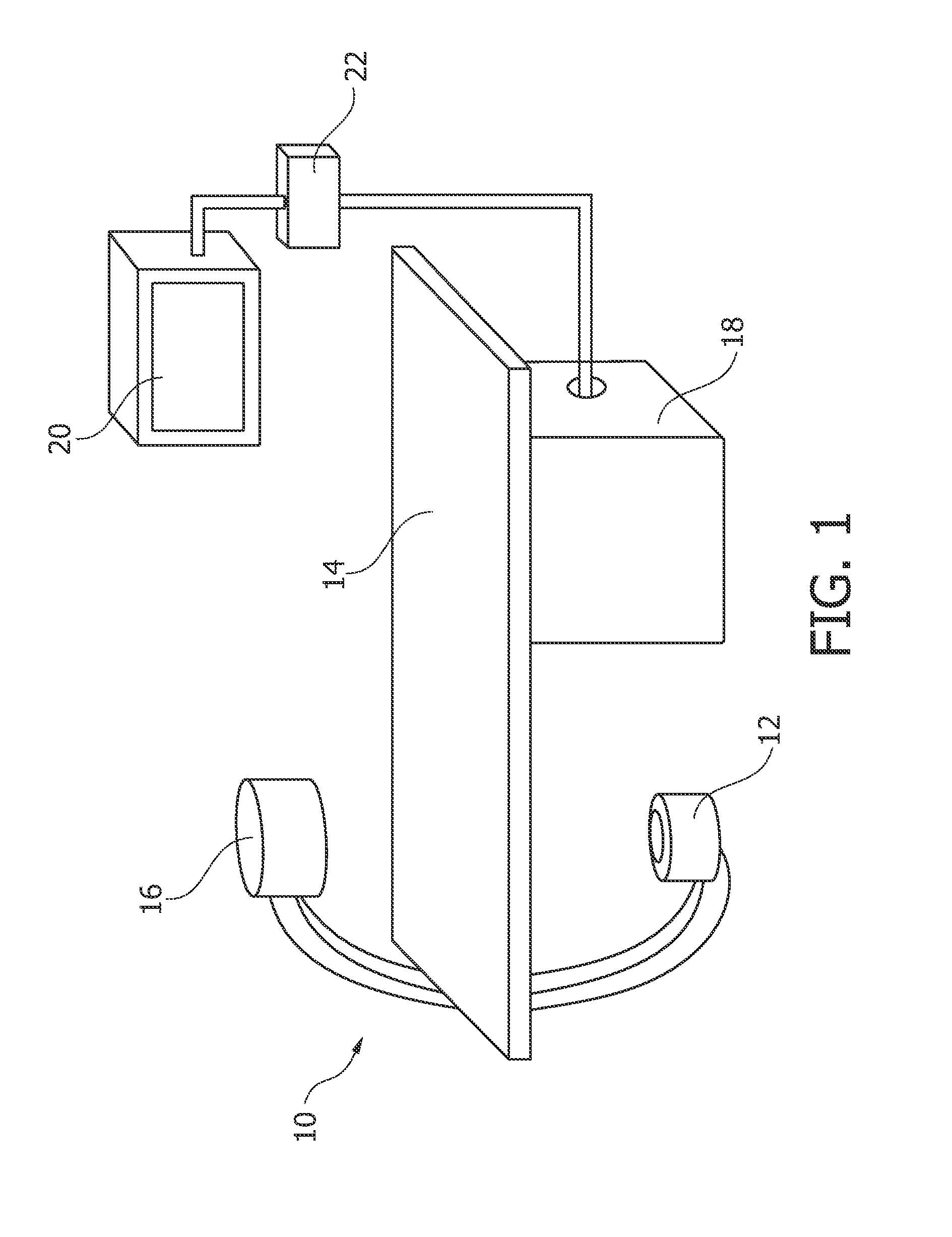
[0051]FIG. 1 schematically shows an X-ray imaging system 10 with a medical viewing system for automatically positioning of an X-ray image acquisition device.

[0052]The X-ray imaging system 10 comprises an X-ray image acquisition device with a source of X-ray radiation 12 provided to generate X-ray radiation. A table 14 is provided to receive an object to be examined. Further, an X-ray image detection module 16 is located opposite the source of X-ray radiation 12. During the radiation procedure, the examined object is located between the source of X-ray radiation 12 and the detection module 16. The latter sends data to a data processing unit or a calculation unit 18, which is connected to both the X-ray image detection module 16 and the X-ray radiation source 12. The calculation unit 18 is exemplarily located underneath the table 14 for saving space within the examination room. It is clear that it could also be located at a different place, such as in a different room or a different l...


PUM


Abstract

In a method for positioning an X-ray image acquisition device a straight reference plane (30) intersecting a three-dimensional representation of the object, a center point (34) within the intersection of the object, a normal vector (38) to the reference plane and at least one tangential vector (40) within the reference plane are created. Thereafter, the reference plane, the object's frame of reference and the X-ray image acquisition's frame of reference are registered. At least one viewing direction derived from the normal vector (38) and / or at least one tangential vector (40) is defined, wherein the X-ray image acquisition device is adjusted to the geometrical parameters of the X-ray image acquisition device. Thereby, planned and stored optimal viewing directions may be made available by a single push of a button, leading to automatically positioning of the X-ray image acquisition device and a much faster adjustment of the live guidance image, thus resulting in less exposure of radiation as well as a less cumbersome adjustment procedure. Furthermore a more optimal deployment of the interventional devices can be reached, since they can be more accurately positioned.

Description

FIELD OF THE INVENTION[0001]The invention relates to a method for positioning an X-ray image acquisition device, a medical viewing system comprising an X-ray image acquisition device and adapted for automatically positioning the X-ray image acquisition device, a computer program element for conducting the method for positioning an X-ray image acquisition device and a computer readable medium.BACKGROUND OF THE INVENTION[0002]Structural heart disease includes many conditions or diseases that may affect the heart muscle itself, the constitution of the heart and the heart valves that control the flow of blood in an out of the heart. Structural heart disorders may already be present at birth or they may develop later in life and can be caused by several conditions. For example, coronary artery diseases may cause blockages of the heart's arteries. It is common to conduct minimal invasive treatment in order to improve the heart condition. For example, insufficiency or stenosis of the heart...

Claims


Application Information

Patent Timeline
IPC IPC(8): A61B6/02
CPCA61B6/503A61B6/547A61B6/504
Inventor RUIJTERS, DANIEL SIMON ANNADENISSEN, SANDERBAKKER, NICOLAAS HYLKE
Owner KONINKLIJKE PHILIPS ELECTRONICS NV
Learn More