
Ultrasonic underwater pager

a pager and ultrasonic technology, applied in the field of pagers, can solve the problems of increasing the cost of manufacturing ultrasonic communication devices, communication is possible, and the fundamental difficulty of achieving water tightness, and achieves the effect of facilitating ultrasonic wave propagation and simplifying the structur

Inactive Publication Date: 2012-07-26
KYUNGWON IND
View PDF8 Cites 3 Cited by
  • Summary
  • Abstract
  • Description
  • Claims
  • Application Information

AI Technical Summary

Benefits of technology

[0009]Accordingly, the present invention has been made keeping in mind the above problems occurring in the prior art, and an object of the present invention is to provide an ultrasonic underwater pager, which has a simplified structure so that the pager is watertight and can be used underwater without a hole being formed in the outer wall of a casing, and which has a structure in which an ultrasonic transducer is installed in a raised position in the casing using a molding process so that the propagation of ultrasonic waves is facilitated.
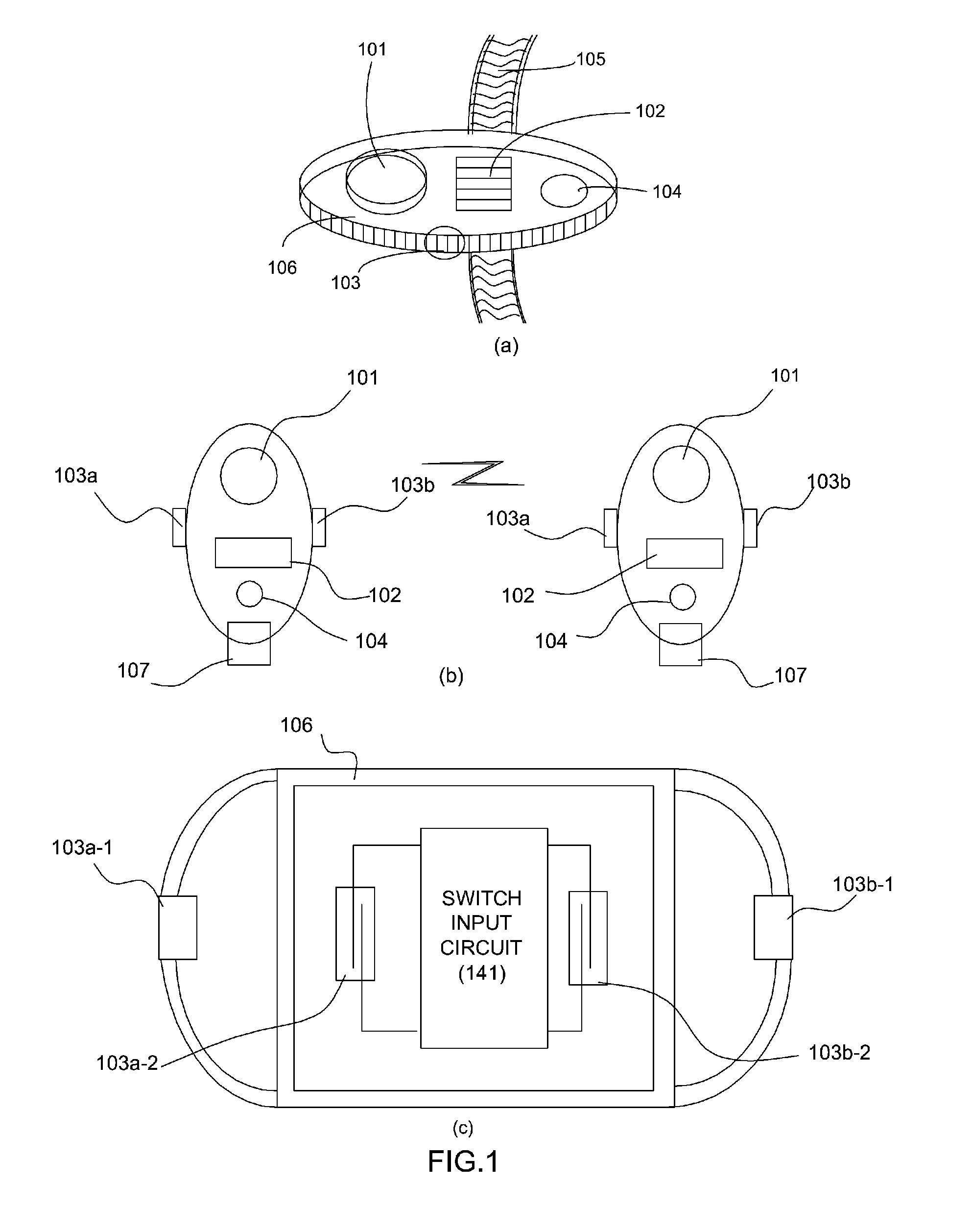
[0012]Yet another object of the present invention is to provide an ultrasonic underwater pager, which can provide a warning related to the results of communication in the form of sound or light using a buzzer, and can perform power switching using the magnetic phenomenon between a magnet and a reed switch, wherein instead of the buzzer, a vibration motor capable of generating a vibration can also be used.
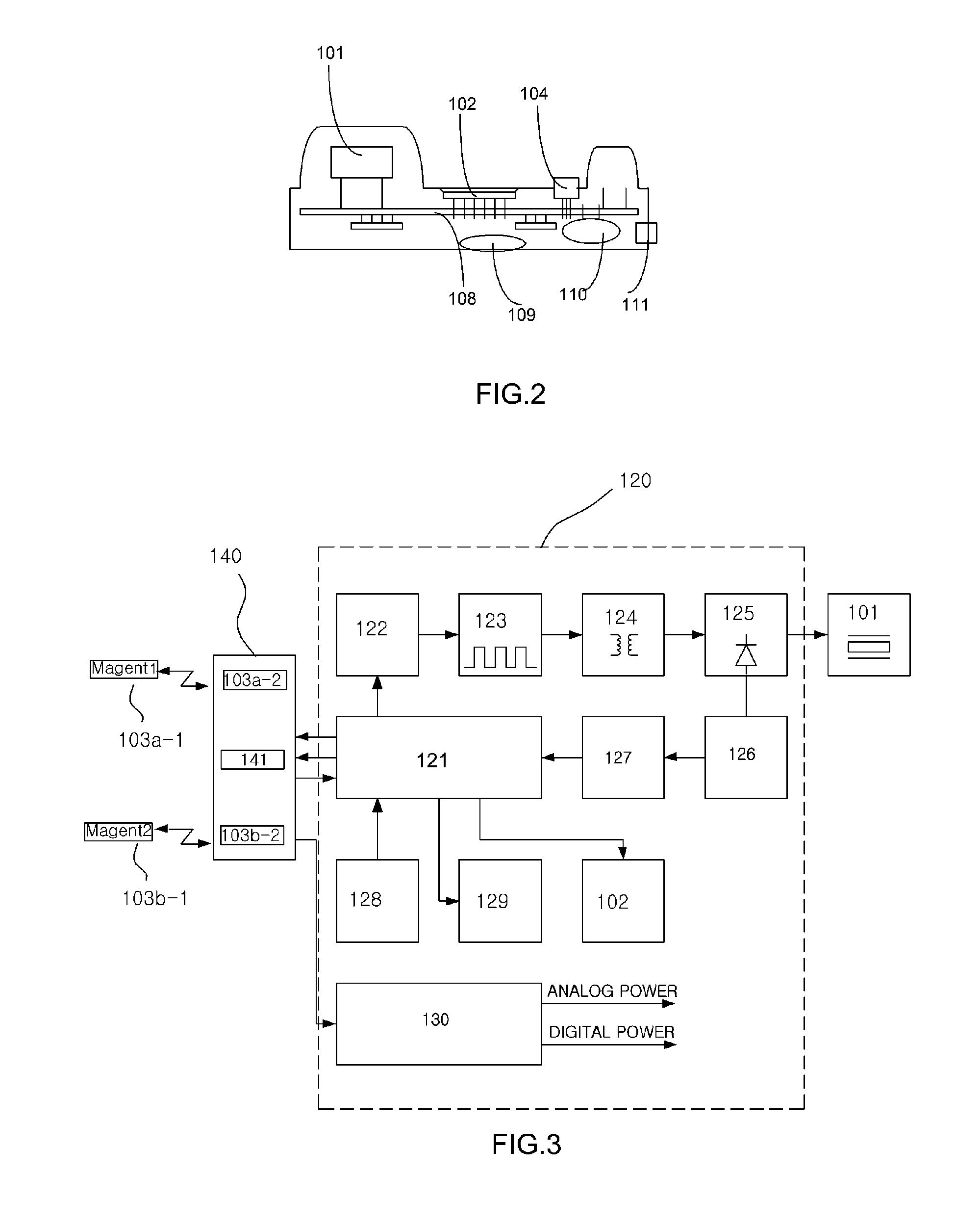
[0015]Preferably, the electronic circuit unit may include a digital signal control unit for generating a transmission signal and analyzing a received signal; a switching driving unit for receiving a switching signal and a transmission trigger signal from the digital signal control unit, and performing low-current switching on an initially generated transmission signal; a high-current switching unit for performing high-current switching on the low-current switched transmission signal; a matching unit for increasing switching efficiency of the high-current switching unit and enabling maximum power to be transferred; a diode coupling unit for transferring the transmission signal which has been high-current switched by the high-current switching unit to the ultrasonic transducer, and receiving the ultrasonic signal from the ultrasonic transducer; a received signal amplification unit for filtering and amplifying the signal received from the diode coupling unit; an envelope detector for detecting an envelope of the amplified signal; and a power control circuit for controlling supply of external power.

Problems solved by technology

However, such an ultrasonic communication device using voice is problematic because the structure thereof is complicated compared to the communication schemes in which simple messages are exchanged based on analog communication, thus increasing the cost of manufacturing the ultrasonic communication device.
Further, an ultrasonic communication device is disadvantageous in that since it is based on voice communication, communication is possible only when a voice can be heard.
Such a switch is implemented as a structure in which a hole is formed in the outer wall of a watertight casing and the switch is installed in the hole, and thus there is a fundamental difficulty when achieving watertightness.

Method used


Image

  • Ultrasonic underwater pager
  • Ultrasonic underwater pager
  • Ultrasonic underwater pager

Examples


Embodiment Construction

[0028]Hereinafter, embodiments of the present invention will be described in detail with reference to the attached drawings. If in the specification, detailed descriptions of well-known functions or configurations may unnecessarily make the gist of the present invention obscure, the detailed descriptions will be omitted, and repetitive descriptions will also be omitted.

[0029]In the present specification, the case where any one first component “transmits” data or signals to another second component means that the first component may transmit the data or signals to the second component either directly or via at least one third component.

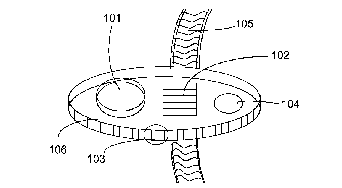
[0030]FIG. 1 is a view showing an ultrasonic underwater pager according to an embodiment of the present invention, and FIG. 2 is a sectional view showing the internal construction of the ultrasonic underwater pager according to an embodiment of the present invention. Referring to FIGS. 1 and 2, an ultrasonic underwater pager 100 includes an ultrasonic ...


PUM


Abstract

Disclosed herein is an underwater pager configured such that a hole is not formed in the outer wall of a casing. The ultrasonic underwater pager includes an ultrasonic transducer for transmitting or receiving ultrasonic signals. An electronic circuit unit generates an ultrasonic signal and analyzes a received ultrasonic signal. A switch unit is switched using a magnetic phenomenon and is configured to supply power to the electronic circuit unit and transmit external commands to the electronic circuit unit. A watertight casing is configured such that the ultrasonic transducer, the electronic circuit unit, and the switch unit are installed in the watertight casing, the ultrasonic transducer being installed in a raised position in the watertight casing using a molding process. A magnet is attached to a rubber cover connected to an outside of the watertight casing, and is configured to switch on / off the switch unit using a magnetic phenomenon.

Description

BACKGROUND OF THE INVENTION[0001]1. Field of the Invention[0002]The present invention relates, in general, to pagers, and, more particularly, to an ultrasonic underwater pager, which assigns a group identification code and an individual identification code under the water and then transmits or receives signals to or from a specific group or a specific individual person while enabling the structure of the pager to be simplified and facilitating the propagation of ultrasonic waves.[0003]2. Description of the Related Art[0004]Conventional ultrasonic communication devices were developed mainly to perform voice communication underwater, and thus signals were able to be received based on one-to-one communication or one-to-many communication.[0005]Such an ultrasonic communication device has used a method of transferring voice signals to a Single Side-Band (SSB) frequency band and radiating the voice signals into the water through an ultrasonic transducer.[0006]However, such an ultrasonic c...

Claims


Application Information

Patent Timeline
IPC IPC(8): H04B11/00A45F5/00
CPCA45F5/00H04B13/02H04B11/00A45F2005/008H04B5/00
Inventor CHOE, MIHEUNGKIM, KYOUNGWON
Owner KYUNGWON IND
Learn More