

Removing Dust Using A Hand Pump
a hand pump and dust removal technology, applied in the field of manual hand pumps, can solve the problems of a large flame, a long time-consuming and labor-intensive process, and a large amount of dust, and achieve the effects of eliminating the many risks associated, reducing labor intensity, and reducing labor intensity
- Summary
- Abstract
- Description
- Claims
- Application Information
AI Technical Summary
Benefits of technology
Problems solved by technology
Method used
Image

Examples
first embodiment
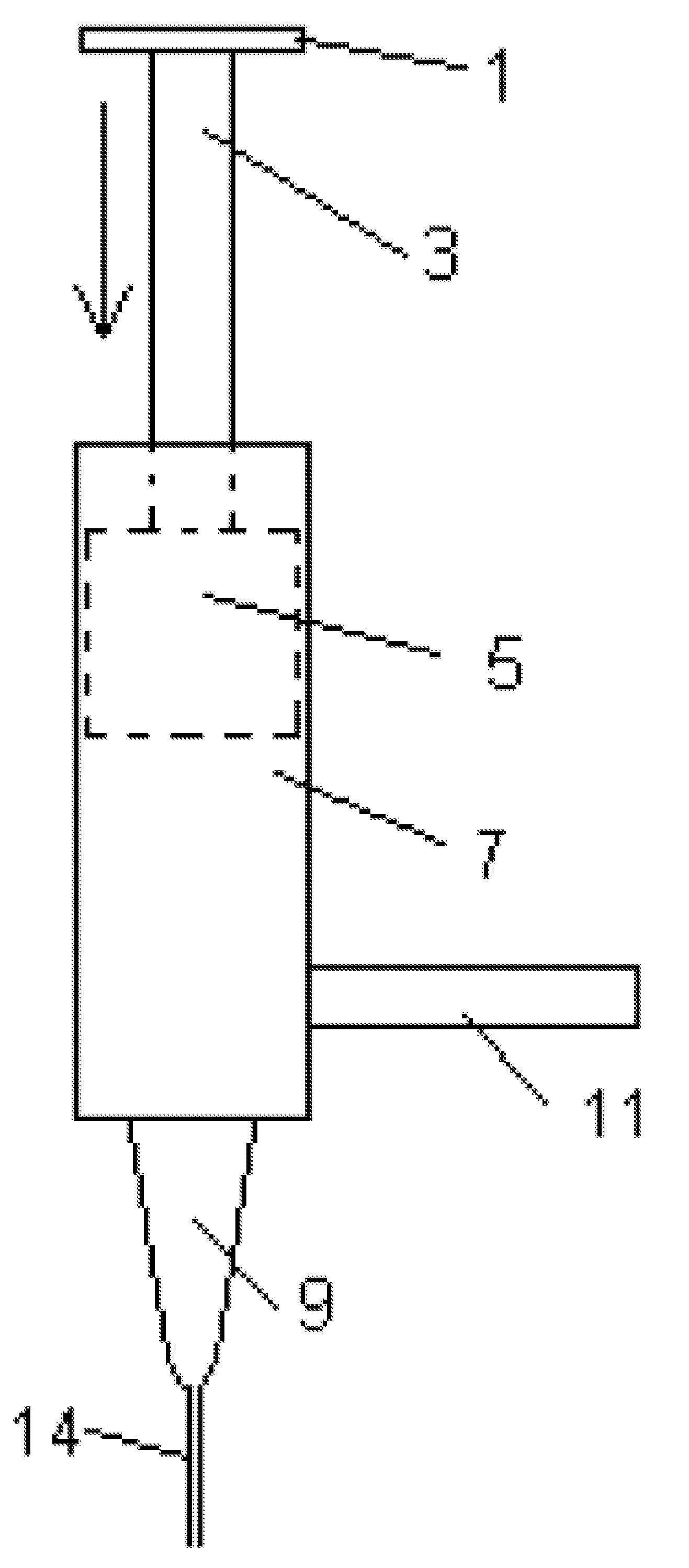
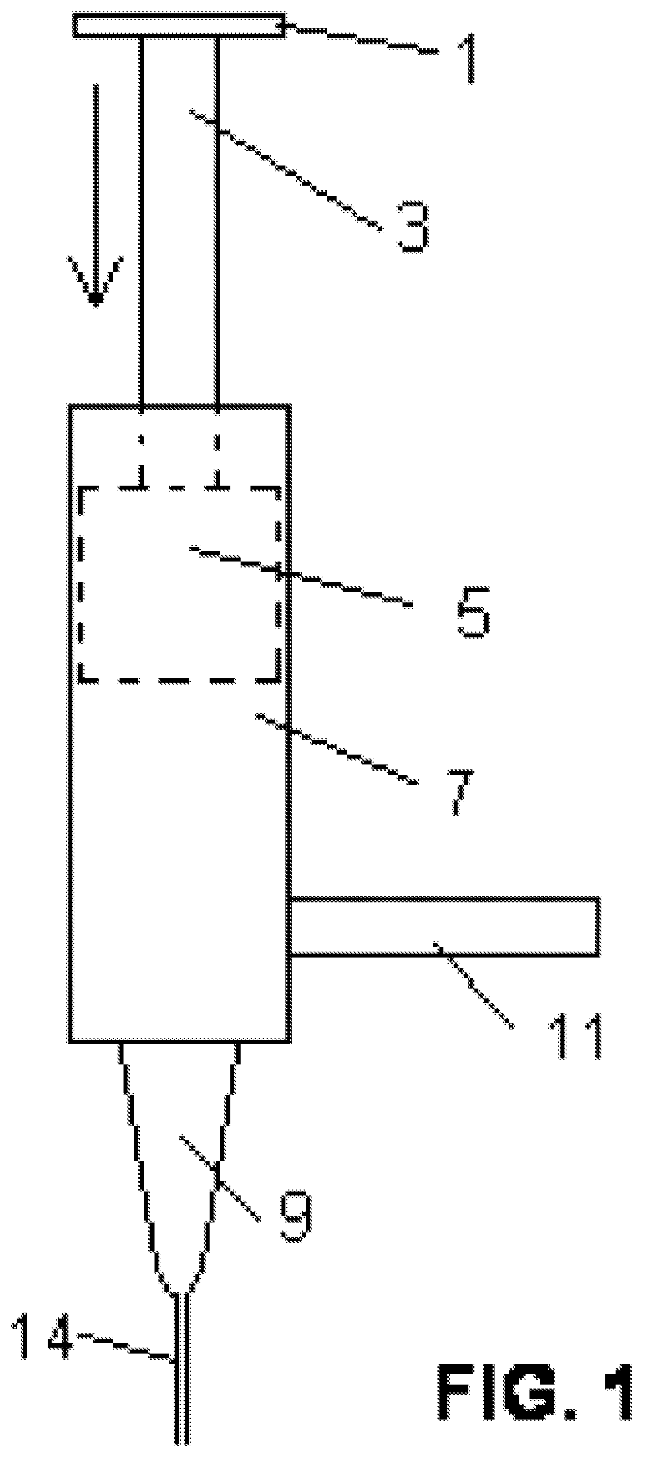
[0067]The first embodiment will be described with reference to FIG. 1. Directions of airflow throughout the following descriptions will be given in agreement with the directions shown in the drawings. In the following descriptions, “forward” refers to the direction which is toward the nozzle and “rearward” refers to the direction which is toward the handle. FIG. 1 is an example of a manual air pump for removing dust from computer related equipment such as keyboards, printers, scanners, copiers and monitors. The air pump has two handles 1, 11. The first handle 1 is attached to a bar 3 that is attached to a piston 5 which has a proximal end and a distal end. The piston 5 moves within the cylinder 7 which has a rearward (proximal) end and a forward (distal) end. The pump has preferably a non-flexible neck or nozzle 9 to direct the air flow. Preferably, the nozzle 9 is conical in shape to optimize the control over the air flow possessed by the operator. The outlet opening of the nozzle ...
third embodiment
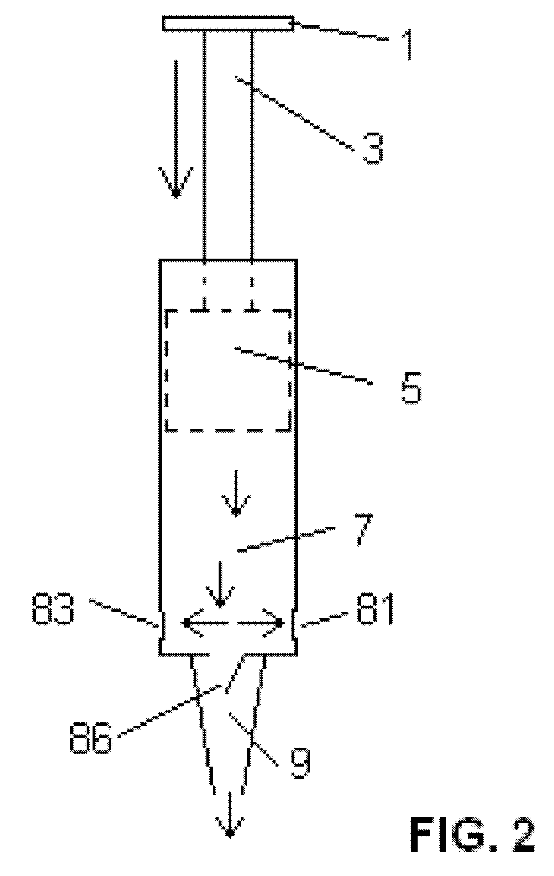
[0072]FIG. 5 shows what happens in response to a downward stroke in the pump of the third embodiment shown in FIG. 4. When the cylinder 7 is forced downward, the side valves 81, 83 open to permit the escape of air carrying dust and debris from inside the cylinder 7. Simultaneously, the high air pressure forces the forward valve 86 to close, preventing the air from escaping through the nozzle 9 opening. When the piston 3 is forced up by manual action, as in FIG. 4, dust and debris from the computer parts are sucked into the cylinder 7 and when the piston 5 is forced down, the dust and debris are forced out of the cylinder 7 at a location removed from the computer parts. This is especially true when a stiff tube 14 is attached to the nozzle 9. Thus, the three valves 81, 83, 86 affect the manipulative process in that they allow the nozzle 9 or stiff tube 14 to be held near the computer parts when the pump is used in a vacuuming mode and preventing dust from being returned to the comput...
fourth embodiment
[0073]FIG. 6 illustrates a manual vacuum pump of a This pump is similar to that shown in FIG. 5 except that it has a dust container 92 surrounding the side valves 81, 83 to collect the dust and debris exiting the side valves 81, 83 to prevent the dust from blowing outside of the cylinder 7 into the room. The container 92 has a filter (not shown) that collects the dust while allowing the air to escape. This provides extra protection against dust which enters the pump from being returned to the computer parts. In addition, the pump of FIG. 6 has an optional anti-static conductive wire or band 98 attached to a local ground source 96. The anti-static wire 98 may be permanently attached to a metallic conductive part of the pump. The purpose of the anti-static wire 98 is to discharge any static electricity that may be present in the pump. Static electricity damages electronic equipment. The anti-static wire 98 prevents any damage to the computer equipment caused by static electricity. In...
PUM
 Abstract
Description
Claims
Application Information