Multi-ring Plasma Pyrolysis Chamber

a plasma pyrolysis chamber and multi-ring technology, applied in the direction of combustible gas production, energy input, chemistry apparatus and processes, etc., can solve the problem of additional operational expense of oxygen use, and achieve the effect of reducing pre-heated fuel

Inactive Publication Date: 2012-08-23
OAKS PLASMA
View PDF11 Cites 26 Cited by
  • Summary
  • Abstract
  • Description
  • Claims
  • Application Information

AI Technical Summary

Benefits of technology

[0015]a second step of exposing pre-heated fuel to a steam plasma generated by a steam plasma torch coupling the steam plasma into an annular ring distributor in the chamber and surrounding the pre-heated fuel, coupling the steam plasma in the annular ring distributor to the pre-heated fuel using a plurality of apertures, thereby oxidizing and reducing the pre-heated fuel and generating combustible gasses and waste products of ash and slag; a third step of gasification of the ash residual carbon by injecting an air plasma into the oxidized and reduced fuel with a half annular ring distributor having a plurality of apertures directing the air plasma into the outlet zone;

Problems solved by technology

The pryrolysis apparatus and method operates at maximum efficiency for fuel generation and waste volume reduction at increased temperatures, and as described above, these elevated temperatures may be reached using oxygen enhanced combustion air, but the use of oxygen represents an additional operational expense.

Method used


Image

  • Multi-ring Plasma Pyrolysis Chamber
  • Multi-ring Plasma Pyrolysis Chamber
  • Multi-ring Plasma Pyrolysis Chamber

Examples


Embodiment Construction

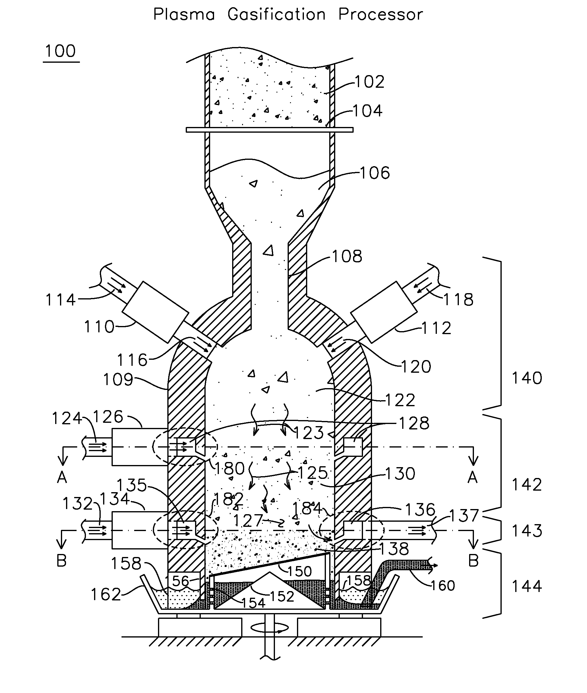
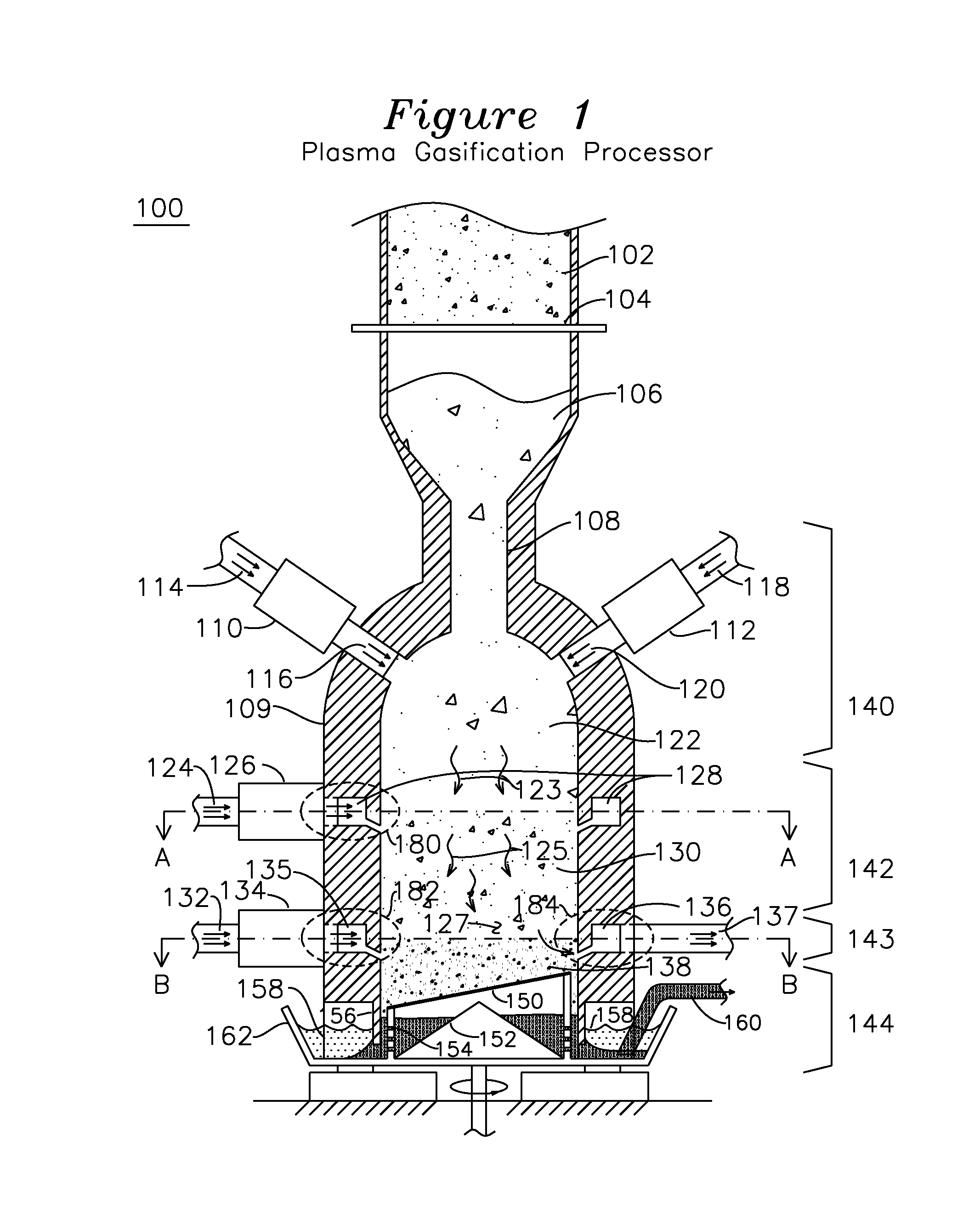
[0022]The present invention describes an apparatus and method for pyrolytic waste recovery which can extract energy in the form of combustible gases from a wide variety of heterogeneous organic materials including municipal refuse, biomass, agriculture wastes, wood and forest product processing wastes, hazardous wastes, petroleum coke, coal or oil shale, individually or as mixtures. Depending on the nature of the input fuel, the resultant combustible gas is suitable use as a fuel for electric power generation, for conversion to synthetic hydrocarbons, hydrogen, or other valuable chemicals. In one embodiment of the invention, the combustible gas includes H2 and CO and a steam plasma is injected in the oxidation and reduction zone which generates these gasses, the steam plasma containing sufficient energy to compensate for the endothermic heat required to generate these combustible gasses. In another embodiment of the invention, the fuel is wood chips or other biomass fuel. The instan...


PUM

PropertyMeasurementUnit
arc lengthaaaaaaaaaa
temperatureaaaaaaaaaa

Abstract

A pyrolysis chamber for the extraction of combustible gasses from biomass waste such as wood chips has a gravity fed chamber, where fuel passes, in succession, through a pre-heating zone, an oxidation and reduction zone, a gas outlet zone and a solids offloading zone. The pre-heating zone has plasma torches which direct an air plasma into the chamber, thereby pre-heating the fuel to a temperature of 1200-1500° C., after which the fuel enters the oxidation and reduction zone, where it is exposed to a steam plasma of 1500° C. which travels through plasma torches to an annular ring distributor surrounding the chamber and having apertures directing the steam plasma into the chamber, thereby providing enhanced generation of combustible gasses of CO and H2. The combustible gasses are removed in the gas outlet zone, which has a half annular ring collector removing combustible gasses out of the chamber and half annular ring distributor injecting an air plasma into the chamber for gasification of the ash residual carbon. A solids offloading part has a rotating grate for the removal of ash and slag for delivery to a water trough.

Description

FIELD OF THE INVENTION[0001]The current invention is drawn to the field of Pyrolysis chambers and processes. More specifically, the invention relates to a top-loading Pyrolysis chamber for organic fuel such as wood chips, the chamber having a plurality of air plasma torches for pre-heating, steam plasma torches coupled to an enclosed annular ring distributor for uniform steam plasma application during oxidation and reduction, air plasma torches coupled to an enclosed half annular ring distributor for introduction of air plasma into outlet zone for removing ash and slag and a half annular ring collector for collection and offloading of combustible gasses.BACKGROUND OF THE INVENTION[0002]Pyrolysis is commonly defined as the thermal decomposition of an organic fuel in an environment of less-than-stoichiometric oxygen, and devices utilizing this process are known as partial oxidation reactors. Devices utilizing organic combustion include coal-based gasification projects, which use direc...

Claims


Application Information

Patent Timeline
Patent Type & Authority Applications(United States)
IPC IPC(8): C10J3/48C10J3/72
CPCC10J3/24C10J3/26C10J3/42C10J3/74Y02E20/16C10J2300/0956C10J2300/0976C10J2300/1238C10J2300/092Y02P20/129
Inventor RUTBERG, ALEXANDER FILIPPOVICHRUTBERG, PHILIPP GRIGOREVICHBZATSEV, ALEXANDZ NIKOLAEVICHPOPOV, VIKTOR YEVGENYEVICH
Owner OAKS PLASMA
Why Eureka
Try Eureka