System for Analysing Gas From Strata Being Drilled Under High Mud Flows

Active Publication Date: 2012-08-30
GRAY IAN
View PDF8 Cites 13 Cited by
  • Summary
  • Abstract
  • Description
  • Claims
  • Application Information

AI Technical Summary

Benefits of technology

[0011]According to this embodiment of the invention designed to handle higher drilling fluid flow rates, the fluids passing from the port below the rotary seal are directed into an initial separator which separates the gas from the liquids and solids. The preferred embodiment of this initial separator is a large cyclonic device where the liquid level is held fairly static by having its base submersed in an open vessel with a fixed level overflow. The liquid and solid stream from the separator are run across a shale shaker (vibrating screen) or sieve bend which separates out the coarser size fraction of cuttings from the fines and drilling fluid. These coarser cuttings are then collected and desorbed in the conventional manner. This involves placing them in a canister and measuring the ra

Problems solved by technology

The conventional mud logging systems lack quantitative estimates of gas release volume because of the nature of the sampling process where air is drawn from above the mud in the belly of a shaker or some other area.
Invariably, gas is lost during the transit period fro

Method used


Image

  • System for Analysing Gas From Strata Being Drilled Under High Mud Flows
  • System for Analysing Gas From Strata Being Drilled Under High Mud Flows

Examples


Embodiment Construction

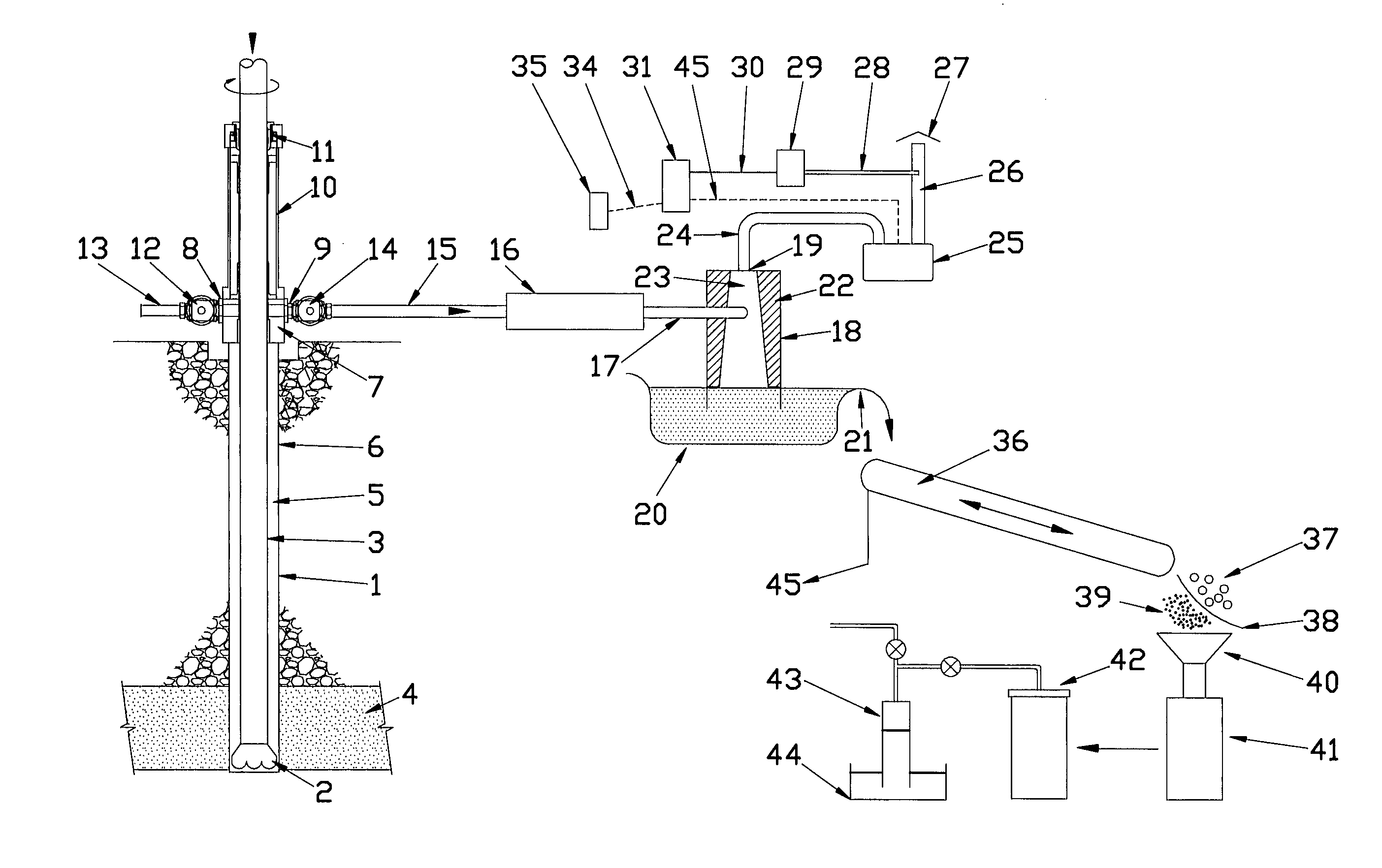
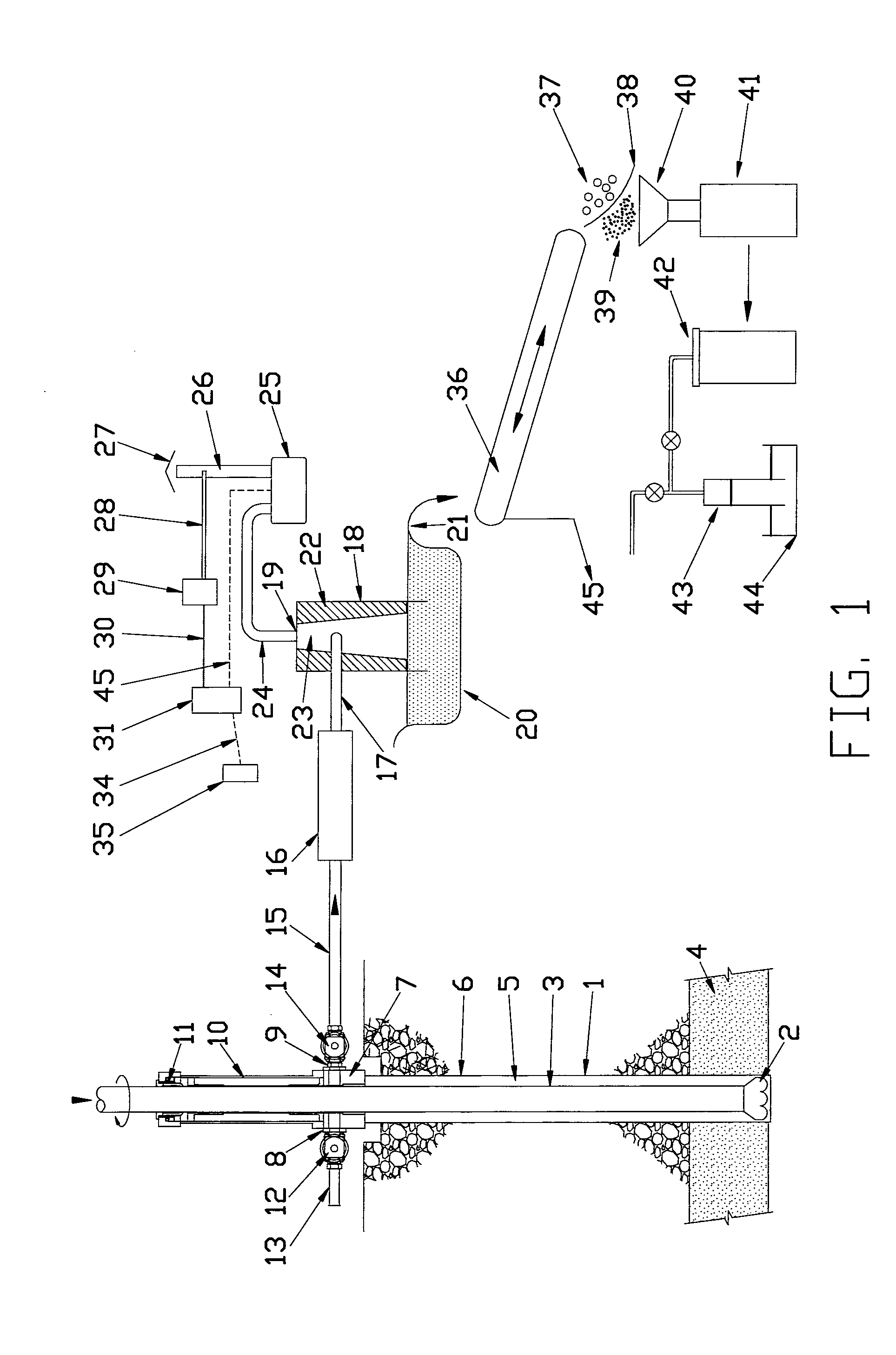
[0016]FIG. 1 illustrates a downhole drilling operation of the type well adapted for analysing gasses obtained from a substrata coal seam. Over long periods of time, the coal seam absorbs or generates gasses which are contained in the coal material and its pores. It is to be understood that the principles and concepts of the invention can be employed in many other drilling situations and applications, including oil and gas shales, and other geological formations. The gas recovery and processing system shown in FIG. 1 illustrates a wellhead providing a closed system for recovering the drill liquid, cuttings and any dcsorbed gas from the down hole formation. The drill liquid, cuttings and desorbed gas are coupled from the wellhead in a closed separator system in which the gas is separated from the drill fluid and cuttings. The desorbed gas is then coupled to the gas processing equipment to determine predefined parameters, such as the extent of gas and / or the gas constituents in the for...


PUM


Abstract

A gas analysis system for determining the gas content of subterranean strata. A boring operation is commenced to form a borehole into or through a subterranean formation, such as a coal or shale formation to determine the gas content thereof. The drill fluid, cuttings and any desorbed gas is carried from the downhole location to surface analysing equipment in a closed system, so that the desorbed gases are not exposed to the air. The drill stem is capped or sealed at the surface, as well as the wellbore annulus to effectively seal the drill liquid, cuttings and desorbed gasses. The drill fluid, cuttings and desorbed gasses from the formation are coupled from the wellhead apparatus to the gas processing equipment via a closed system so that the constituents and volume of the gas can be determined.

Description

RELATED PATENT APPLICATIONS[0001]This PCT application supplements PCT / AU200900403 application filed on 2 Apr. 2009, and also claims the further benefit of Australian provisional application 2009905663 filed on 19 Nov. 2009. This application provides an additional embodiment of the invention described in these previous applications.TECHNICAL FIELD OF THE INVENTION[0002]The present invention relates in general to hydrocarbon drilling operations, and more particularly to methods and apparatus for analysing gas desorbed in the drilling mud during the drilling operation.BACKGROUND OF THE INVENTION[0003]Mud logging has been used for a long time in petroleum drilling to determine the approximate location of gas bearing strata during the drilling process. In particular, mud logging involves the process of examining the drill cuttings extracted from the drilling mud to identify gas, hydrocarbon and other constituents which exist at the particular location of the drill bit. To that end, a gas...

Claims


Application Information

Patent Timeline
IPC IPC(8): E21B49/00
CPCE21B21/01E21B49/005E21B21/067
Inventor GRAY, IAN
Owner GRAY IAN
Why Eureka
Try Eureka