Method and system for evaluating electrical connections between an motor controller and motor

a technology of electrical connections and motor controllers, applied in the direction of dynamo-electric converter control, dc motor rotation control, instruments, etc., can solve the problem of difficult to determine efficiently and quickly whether the electrical connection between a multi-phase motor and the motor controller is correct, and achieves the effect of reducing the difficulty of determining the electrical connection efficiency and speed

Active Publication Date: 2012-08-30
DEERE & CO
View PDF1 Cites 35 Cited by
  • Summary
  • Abstract
  • Description
  • Claims
  • Application Information

AI Technical Summary

Benefits of technology

[0004]In accordance with one embodiment, a method and system is presented for evaluating electrical connections between a motor controller and motor. For example, a method and system is presented for determining whether a multi-phase motor is properly connected to an inverter with respect to a phase leads sequence. In a diagnostic mode, a data processor, a diagnostic computer, or d-q axis current generation manager establishes or provides a monotonically varying test sequence of test rotor angular positions associated with application of corresponding pairs of direct d-q-axis voltage commands to the motor. Each of the pairs of direct d-q axis voltage commands comprises a direct-axis command and a quadrature-axis command. The data processor or pulse width modulation generation module converts or transforms the direct d-q-axis voltage commands into three phase voltages for each corresponding input phase terminal of the multi-phase motor. The pulse width modulation generation module or the inverter

Problems solved by technology

During assembly, repair or field diagnosis, it can be difficult to determine efficiently and quickly whether the

Method used


Image

  • Method and system for evaluating electrical connections between an motor controller and motor
  • Method and system for evaluating electrical connections between an motor controller and motor
  • Method and system for evaluating electrical connections between an motor controller and motor

Examples


Embodiment Construction

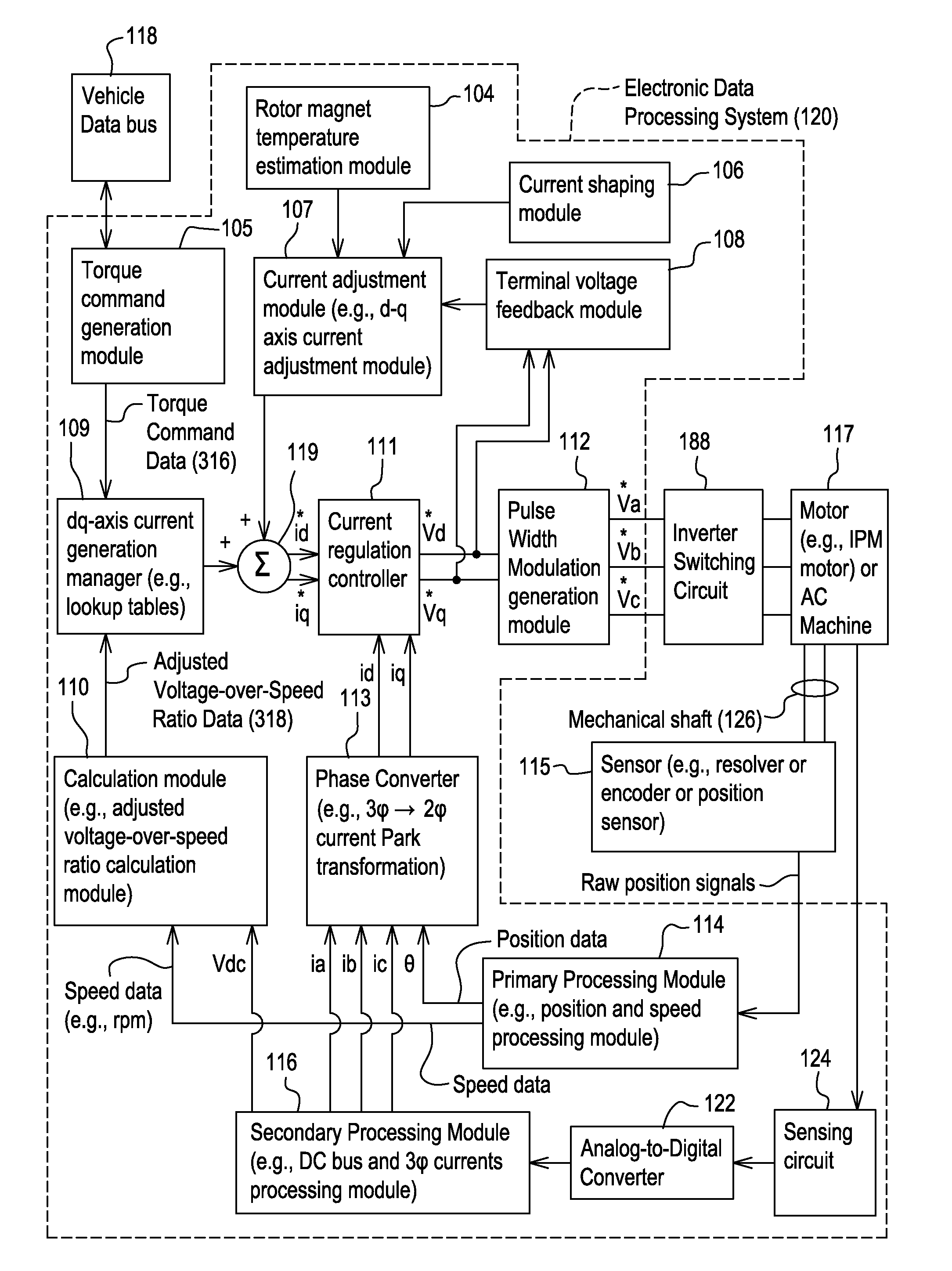
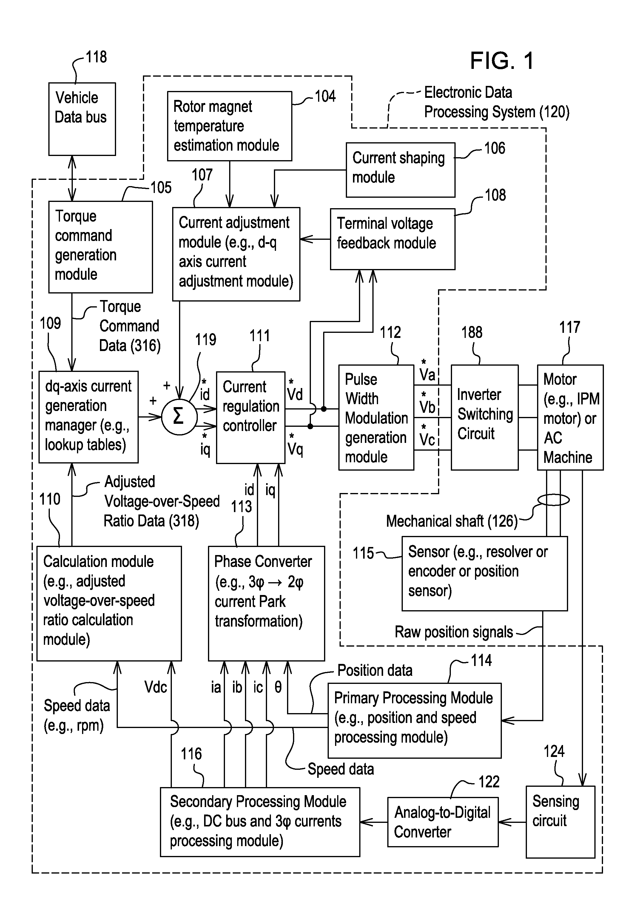
[0009]In accordance with one embodiment, FIG. 1 discloses system for controlling a motor 117 (e.g., an interior permanent magnet (IPM) motor) or another alternating current machine. In one embodiment, the system, aside from the motor 117, may be referred to as an inverter or a motor controller.

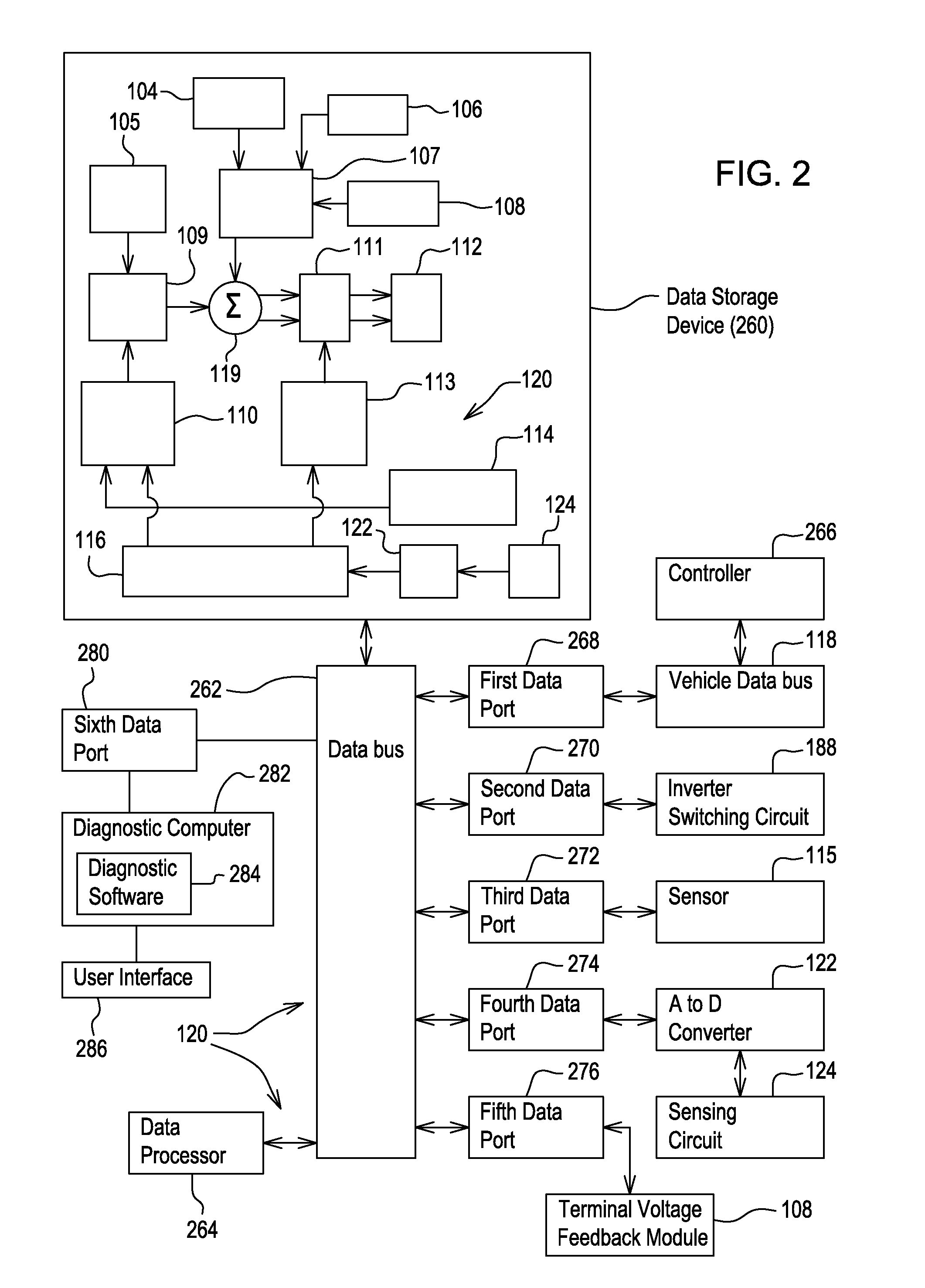
[0010]The system comprises electronic modules, software modules, or both. In one embodiment, the motor controller comprises an electronic data processing system 120 to support storing, processing or execution of software instructions of one or more software modules. The electronic data processing system 120 is indicated by the dashed lines in FIG. 1 and is shown in greater detail in FIG. 2.

[0011]The data processing system 120 is coupled to an inverter circuit 188. The inverter circuit 188 comprises a semiconductor drive circuit that drives or controls switching semiconductors (e.g., insulated gate bipolar transistors (IGBT) or other power transistors) to output control signals for the motor 11...


PUM


Abstract

A pair of direct d-q-axis voltage commands is associated with a monotonically varying test sequence of test rotor angular positions to determine a correct rotational direction of a rotor of the motor in response to application of the pair of direct d-q-axis voltage commands to the motor. The rotor of the motor rotates (e.g., self spins in a diagnostic mode) in response to the applied direct d-q-axis voltage commands and applied monotonically varying test sequence of test rotor angular positions. The primary positioning module or data processor determines that conductor connections between the inverter (e.g., motor controller) and the motor are correct if the calculated shaft speed sign is positive with respect to an applied monotonically varying test sequence of rotor angular positions that monotonically increases.

Description

[0001]This document claims priority based on U.S. provisional application Ser. No. 61 / 446,119, filed on 24 Feb. 2011 and entitled METHOD AND SYSTEM FOR EVALUATING ELECTRICAL CONNECTIONS BETWEEN AN MOTOR CONTROLLER AND MOTOR, under 35 U.S.C. 119(e).FIELD OF THE INVENTION[0002]This invention relates to a method and system for evaluating electrical connections (e.g., or testing for the proper sequence or interconnection of wiring for motor phase leads) between a motor controller and motor.BACKGROUND OF THE INVENTION[0003]An electric motor may comprise an interior permanent magnet (IPM) motor or an IPM synchronous motor, or a multi-phase alternating current motor. During assembly, repair or field diagnosis, it can be difficult to determine efficiently and quickly whether the electrical connections between a motor or multi-phase motor and the motor controller (e.g., inverter) are correct. In the prior art, the phase sequence connection is sometimes checked by first rotating the motor (e....

Claims


Application Information

Patent Timeline
IPC IPC(8): H02P1/22
CPCG01R31/04G01R31/343H02P29/021H02P21/0035G01R31/42G01R31/66H02P21/22H02P29/0241H02P7/03
Inventor WU, LONGSHAW, ROBERTGILMAN, ALAN K.
Owner DEERE & CO
Why Eureka
Try Eureka