Multi-way valve, hydraulic device and concrete pump vehicle

a hydraulic device and multi-way valve technology, applied in the direction of fluid couplings, servomotors, liquid fuel engines, etc., can solve the problems of increasing manufacturing costs, complex valve body structure, limited application, etc., and achieves low production costs, simple structure, and effective reduction of energy loss and heat productivity of the system

Inactive Publication Date: 2012-09-06
HUNAN SANY INTELLIGENT CONTROL EQUIP +1
View PDF11 Cites 24 Cited by
  • Summary
  • Abstract
  • Description
  • Claims
  • Application Information

AI Technical Summary

Benefits of technology

[0008]The object of the present invention is to provide a multi-way valve and a hydraulic device having the load-sensitive function so as to enable the flow rate to match the actual load of the actuator. Usage of the multi-way valve and the hydraulic device can reduce the energy loss and heat productivity.
[0009]According to one aspect of a multi-way valve of the present invention, a multi-way valve includes a plurality of parallel combination valves, configured to control corresponding actuators, each of the combination valves comprising a proportional throttle valve and a reversing valve connected in series, an oil inlet of the proportional throttle valve is connected to an main oil inlet, and an oil outlet of the proportional throttle valve is connected to an oil inlet of the reversing valve, an oil outlet of the reversing valve is connected to the main oil return port, the multi-way valve is characterized in that, each of the combination valve further comprising an one-way control valve, configured to obtain the load pressure of corresponding actuator, one side of the one-way control valve is connected to the pipeline between the proportional throttle valve and the actuator; the multi-way valve further comprising a control element, configured to receive the load pressure fed back by each of the one-way control valve and respond to the load pressure to control the hydraulic oil supplied to the actuators. According to the above solution, the practical load of a plurality of actuators can be transferred to the control element, and the control element provides matched flow rate and pressure according to the practical load, thereby reducing energy loss and heat productivity.
[0013]Furthermore, the control element is a three-way flow valve, its oil inlet is connected to the main oil inlet, and its oil return port is connected to the main oil return port, and its oil control port is connected to the oil outlet of the one-way valve or to the oil outlet of the shuttle valve of the first combination valve. It forms a load-sensitive network comprising of one-way valve or shuttle valve and three-way flow valve by providing a three-way flow valve, so that the load-sensitive function can be easily realized.
[0014]According to one improved solution of the present invention, it further comprises an integrated oil line block, on which the main oil inlets and the main oil return ports are provided, the combination valves and the three-way flow valve are mounted on the integrated oil line block. Thus the multi-way valve has the advantages of simple structure and low manufacturing costs.
[0017]The multi-way valve and the hydraulic device according to the present invention have the load-sensitive function, thereby effectively reducing energy loss and heat productivity of the system. The requirements of the motion of the arm support can be met by using the multi-way valve and the hydraulic device according to the above technical solutions to control the motion of the arm support of the concrete pump vehicle, and the multi-way valve and the hydraulic device have the advantages of simple structure, low production costs, low energy loss and heat productivity.

Problems solved by technology

Because this multi-way valve cannot be electrically automatic controlled, it is greatly limited in application.
However, there are at least two oil chambers and oil ports provided in the valve body of the multi-way valve, which leads to the complex structure of the valve body and thereby increasing the manufacturing cost.
The solution adopting the above multi-way valve has the defect of lacking load-sensitive function, the oil pump 6 in the multi-way valve always functions with the maximal discharge capacity under the overfall pressure set by the overflow valve 5, and it cannot match the actual load of the actuator 4 and the required flow rate, so that a lot of energy is wasted and the hydraulic system has great heat productivity.

Method used


Image

  • Multi-way valve, hydraulic device and concrete pump vehicle
  • Multi-way valve, hydraulic device and concrete pump vehicle
  • Multi-way valve, hydraulic device and concrete pump vehicle

Examples


first embodiment

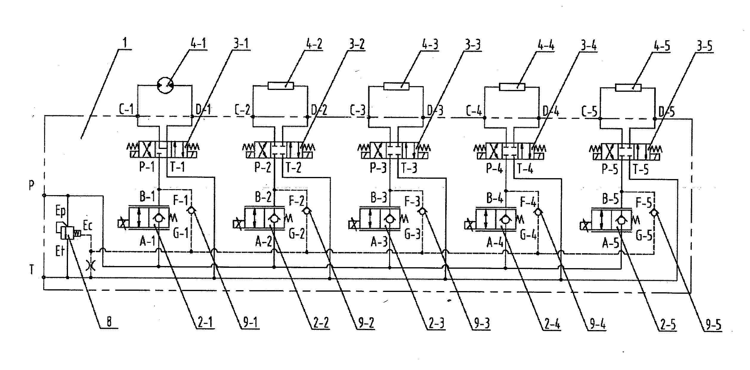
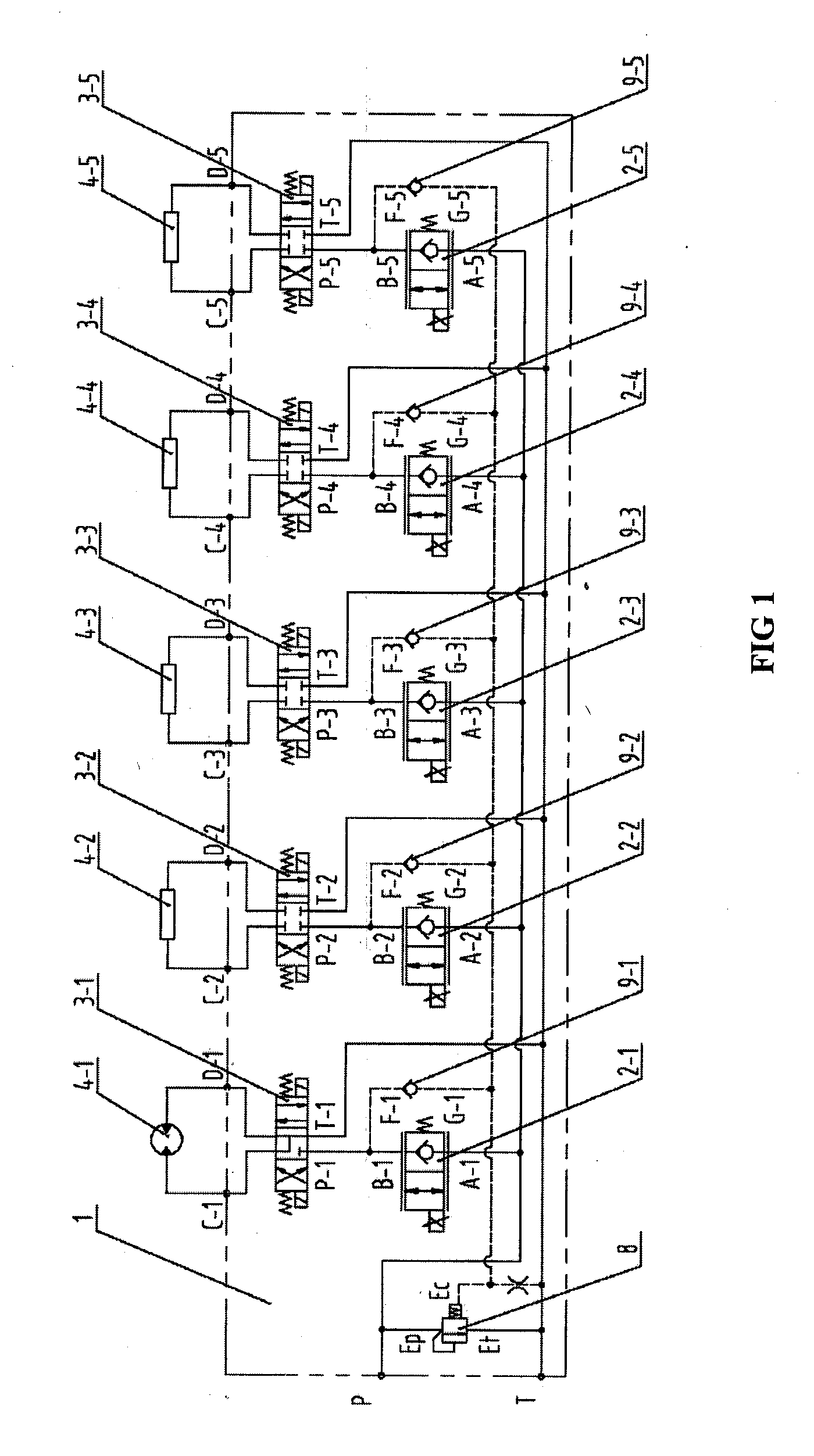
[0046]In the following the working principle of the multi-way valve is described in detail.

[0047]The first electro-hydraulic proportional throttle valve 2-1 controls the flow area at the valve port thereof by the input electrical signal, and thereby it is possible to adjust the hydraulic oil flow rate flowing through the first electro-hydraulic proportional throttle valve 2-1 continuously and proportionally, so that the rotation speed of the hydraulic motor 4-1 can be under control.

[0048]The first electromagnetic reversing valve 3-1 has three working positions, as shown in

[0049]FIG. 1, the first phase in the middle, the second phase on the left and the third phase on the right.

[0050]When the valve core of the first electromagnetic reversing valve 3-1 is in the first phase, the valve core closes the oil inlet P-1, the oil outlet T-1, the first working oil port C-1 and the second working oil port D-1 of the first electromagnetic reversing valve 3-1, the hydraulic oil does not flow th...

third embodiment

[0058]FIG. 5 shows the principle of the multi-way valve according to the present invention, wherein the shuttle valve and the three-way flow valve 8 together realize the load-sensitive function instead of the one-way valve 9-1-9-5. Herein the side of the first oil inlets of the shuttle valve 10-1-10-5 are communicated with oil outlets B-1-B-5 of the electro-hydraulic proportional throttle valve 2-1-2-5, the oil outlet of the first shuttle valve 10-1 is communicated with the oil control port Ec of the three-way flow valve 8. The second oil inlet of the first shuttle valve 10-1 is communicated with the oil outlet of the second shuttle valve 10-2. The second oil inlet of the second shuttle valve 10-2 is communicated with the oil outlet of the third shuttle valve 10-3. The second oil inlet of the third shuttle valve 10-3 is communicated with the oil outlet of the fourth shuttle valve 10-4. The second oil inlet of the fourth shuttle valve 10-4 is communicated with the oil outlet of the f...


PUM


Abstract

A multi-way valve includes a plurality of parallel combination valves for controlling corresponding actuators (4-1-4-5). Each combination valve comprises proportional throttle valves (2-1-2-5) and reversing valves (3-1-3-5). An oil inlet of the proportional throttle valve is communicated with a main oil inlet (P), and an oil outlet of the proportional throttle valve is communicated with an oil inlet of the reversing valve. An oil outlet of the reversing valve is communicated with the main oil return port (T). Wherein, each combination valve further comprises a one-way control valve (9-1-9-5, 10-1-10-5) for obtaining the load pressure of corresponding actuator. One side of the one-way control valve is communicated with a pipeline between the proportional throttle valve and the actuator. The multi-way valve further includes a control element (8) which receives the load pressure fed back by each one-way control valve and responds to the load pressure to control the supply of hydraulic oil for the actuators. The multi-way valve has the load-sensitive function, thereby reducing energy loss and system heat productivity. A hydraulic equipment and a concrete pump vehicle corresponding to the multi-way valve are also provided.

Description

[0001]The present application claims the priority to Chinese patent application No. 200920278542.X filed on Nov. 20, 2009 and entitled “multi-way valve, hydraulic device and concrete pump vehicle”, which is incorporated herein by reference in its entirety.FIELD OF THE INVENTION[0002]The invention relates to the field of construction machinery technology, in particular to a multi-way valve, a hydraulic device and a concrete pump vehicle.BACKGROUND OF THE INVENTION[0003]A multi-way valve is a core control element in construction machinery such as the arm support hydraulic device of a concrete pump vehicle, which is located between the hydraulic pump and the actuator for controlling the flow rate and direction of the hydraulic oil, so that the movement direction and speed of the actuator in the hydraulic device is central controlled and thereby the movement direction and rate of the arm support of the concrete pump vehicle is central controlled. Now the currently used concrete pump veh...

Claims


Application Information

Patent Timeline
Patent Type & Authority Applications(United States)
IPC IPC(8): F15B15/18E04G21/04F15B13/02
CPCF15B11/042F15B2211/413F15B2211/455F15B2211/426F15B2211/41509F15B2211/3138F15B11/161F15B2211/20538F15B2211/20546F15B2211/6052F15B2211/6054F15B2211/71Y10T137/87885
Inventor YI, XIAOGANGLIU, YONGDONGXIANG, YANGHUI
Owner HUNAN SANY INTELLIGENT CONTROL EQUIP
Why Eureka
Try Eureka