Shunt resistor and method for manufacturing the same

a technology of shunt resistor and resistor, which is applied in the field of resistors, can solve the problems of insufficient structure of resistor at super-low, and achieve the effects of excellent shunt resistor in electrical characteristics, high size accuracy, and easy manufacturing

Active Publication Date: 2012-09-13
KOA CORP
View PDF0 Cites 37 Cited by
  • Summary
  • Abstract
  • Description
  • Claims
  • Application Information

AI Technical Summary

Benefits of technology

[0004]The invention has been made basing on above-mentioned circumstances. Therefore objects of the invention are to provide a shunt resistor and manufacturing method thereof, which is excellent in current detection accuracy, which is able to reduce temperature drift, which is able to make structure small and compact, and which improves operability to use.Solution to Problem
[0007]According to the invention, each component can be machined easily, and high size accuracy can be obtained upon each component. And an excellent shunt resistor in electrical characteristics has been produced since steady current pathway has been achieved. Also, by inserting voltage detection electrode that has detection terminal for detecting voltage between the resistance body and the main electrode as a bonding part, since accuracy of position where voltage detection terminal is formed goes up, then accuracy of voltage detection goes up. In the resistor of super-low resistance value of about 0.1 mΩ, without receiving influence of resistance element of main electrode material, current detection at highly accurate resistance value and low temperature coefficient of resistance that the resistance body possesses becomes possible.

Problems solved by technology

However structure of the resistor is not necessarily enough at super-low resistance value to be excellent in current detection accuracy and to reduce temperature drift.

Method used


Image

  • Shunt resistor and method for manufacturing the same
  • Shunt resistor and method for manufacturing the same
  • Shunt resistor and method for manufacturing the same

Examples


first embodiment

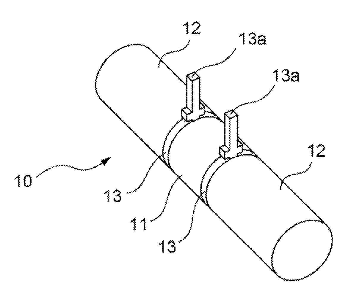
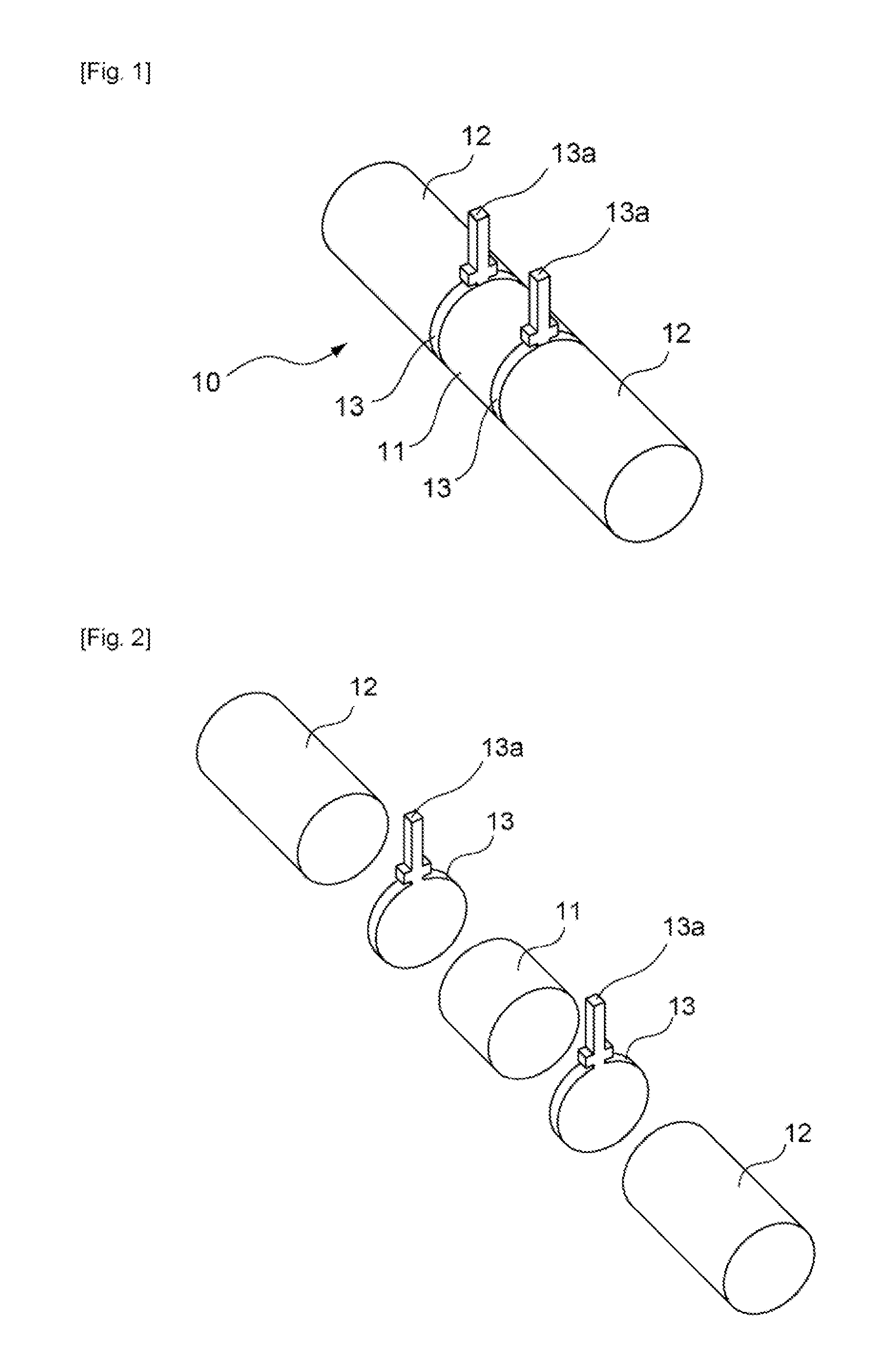
[0031]FIG. 1 shows a shunt resistor of first embodiment of the invention, and FIG. 2 shows an exploded view thereof. The shunt resistor 10 is provided with a columnar resistance body 11 consisting of resistance alloy material such as Manganin, a pair of main columnar electrodes 12,12 consisting of highly conductive metal material such as copper, which is separated from the resistance body, and a pair of plate-type voltage detection electrodes 13,13 consisting of highly conductive metal material such as copper, which is separated from the main electrode. Voltage detection electrode 13 has a projection part projecting from the electrode 13, and a terminal of voltage detection circuit will be connected thereto by welding etc.

[0032]As shown in the Figure, voltage detection electrode 13 is provided and bonded between resistance body 11 and main electrode 12. And, end faces of plate-shaped voltage detection electrode 13 and end faces of columnar main electrode 12 are fixed to both end fac...

second embodiment

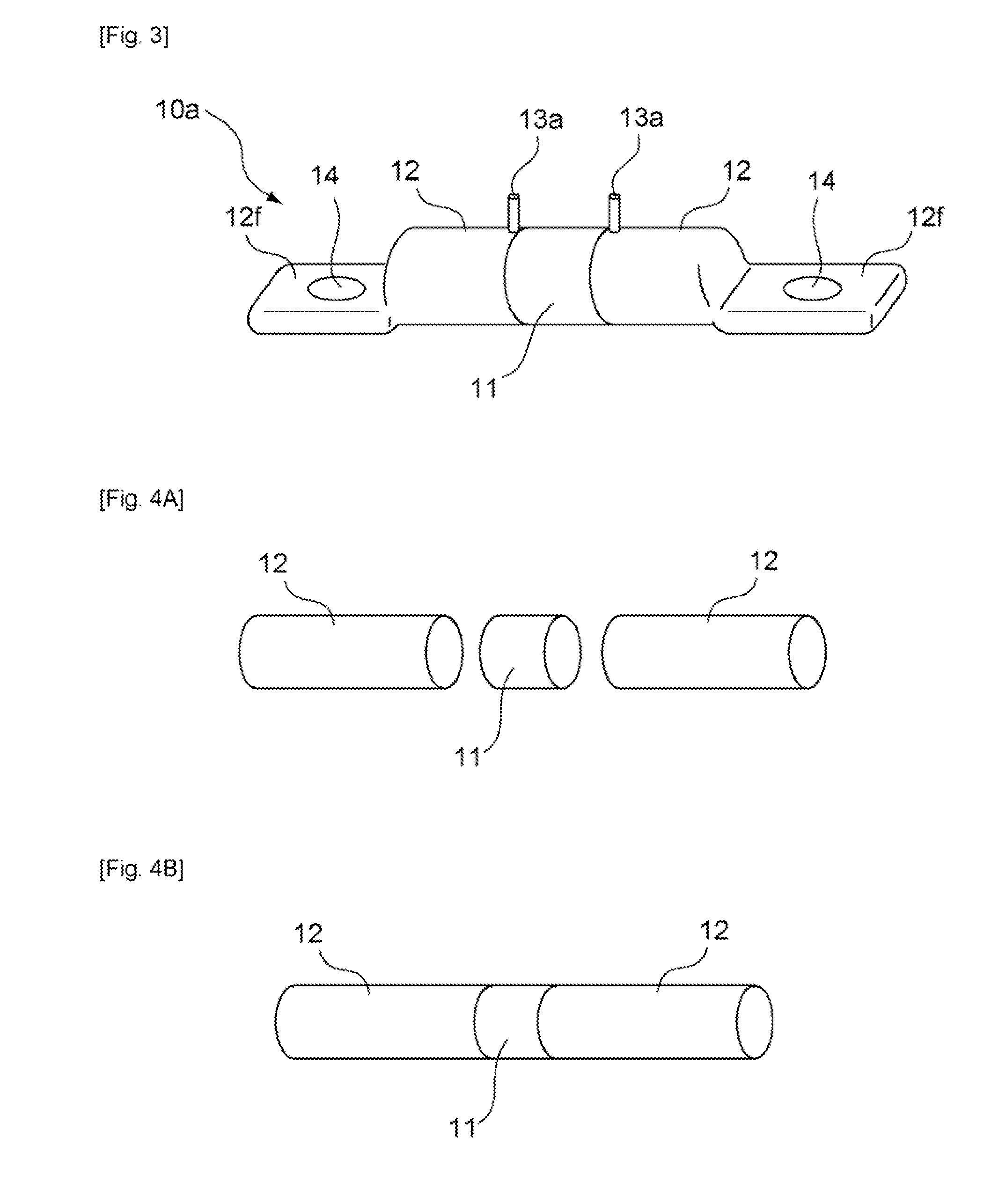
[0045]FIG. 3 shows shunt resistor of second embodiment of the invention. The shunt resistor 10a has a structure that flatness part 12f,12f are formed at both ends of electrodes 12,12 that are columnar. The flatness part 12f has opening 14 therein. And, it forms a structure that bus bar connected with battery etc. can be connected and fixed to flatness part by using bolt and nut through opening 14. Opening 14 may be a screw hole, and may fix the bus bar to flatness part 12 by screw stop. Since flatness part 12f is formed, it becomes easy to connect and to fix with bus bar or tabular metal terminal fittings.

[0046]FIG. 4A-4F shows an example of manufacturing process of second embodiment. As shown in FIG. 4A and FIG. 4B, resistance body 11 consisting of alloy material for resistance body such as Manganin etc. and a pair of main electrodes 12,12 consisting of highly electric conductive metal such as copper separated from resistance body are prepared. Resistance body 11 and main electrode...

third embodiment

[0050]FIG. 5 is shunt resistor of third embodiment of the invention. In this example, position of flatness part 12g having opening 14 is formed at almost middle part in height of the resistor. That is, the flatness part is formed at position that passes through central portion in section of the resistor. FIG. 6A and FIG. 6B show an example of the manufacturing process. First, as well as embodiment mentioned above, material that becomes resistance body, material that becomes voltage detection electrode, and material that becomes main electrode are prepared, in addition, wax material is prepared. Voltage detection electrode has detection terminal 13a. Flatness part 12g is formed beforehand at a part of main electrode 12. Opening 14 of flatness part 12g may be formed beforehand, or may be formed after connecting each material.

[0051]In third embodiment, bonding of resistance body 11, voltage detection electrode 13, and main electrode 12 is done by brazing and soldering. The brazing and ...


PUM

PropertyMeasurementUnit
resistanceaaaaaaaaaa
lengthaaaaaaaaaa

Abstract

Provided is a shunt resistor which has an excellent accuracy of current detection and a small temperature drift as well as a compact structure, and improves the operability. The shunt resistor is provided with a resistance body (11), a pair of main electrodes (12, 12) separated from the resistance body, and a pair of voltage detection electrodes (13, 13) separated from the main electrodes. The voltage detection electrodes (13) are provided and fixed between the resistance body (11) and the main electrodes (12). The voltage detection electrode (13) is provided with a detection terminal (13a) to be connected to a terminal of a voltage detection circuit. The resistance body (11) has a columnar shape. The voltage detection electrode (13) and main electrode (12) are fixed to both end faces of the resistance body (11) in the length direction, so that they are opposing each other. The components are bonded by diffusion boding, friction bonding, wax bonding, etc., after abutting the bonding surfaces with each other.

Description

TECHNICAL FIELD[0001]The invention relates to a resistor, especially relating to a shunt resistor consisting of metal material that uses resistance alloy material as resistance body.BACKGROUND ART[0002]The shunt resistor is used for observing electrical charge and discharge of battery current and for preventing the battery trouble beforehand. The shunt resistor is excellent in current detection accuracy, small in current drift, and even if a large current is applied, excessive heat is not generated. The shunt resistor is used in a field where super-low resistance value such as 1 mΩ or less is required, and various structures of shunt resistors have been proposed (for example, refer to Japanese laid open patent publication 2009-216620).[0003]The shunt resistor has cylindrical current terminals (electrodes) on both sides of resistance body, and the terminals are connected directly with cables. And the shunt resistor is used by welding voltage detection terminals to connection space of...

Claims


Application Information

Patent Timeline
Patent Type & Authority Applications(United States)
IPC IPC(8): H01C1/14H01C17/00
CPCG01R1/203Y10T29/49082H01C1/14
Inventor YOSHIOKA, TADAHIKO
Owner KOA CORP
Why Eureka
Try Eureka