Oil well cleaning compositions

a technology of oil wells and compositions, applied in the direction of fluid removal, wellbore/well accessories, chemistry apparatus and processes, etc., can solve the problems of affecting the effectiveness and affecting the efficiency of well production, and requiring extensive well shutdown time, so as to increase the output flow of wells, increase the output flow, and increase the output flow

Inactive Publication Date: 2012-09-20
DYER RICHARD J
View PDF20 Cites 60 Cited by
  • Summary
  • Abstract
  • Description
  • Claims
  • Application Information

AI Technical Summary

Benefits of technology

[0025]In accordance with one embodiment of the present invention, it is an object thereof to provide an improved method using a unique formulation for removing foreign matter from a well to increase the output flow of the well.
[0026]It is another object of the present invention to provide an improved method using a unique formulation in combination with any apparatus to clean the bore hole of the well to incre...

Problems solved by technology

Paraffin and/or asphaltene and scale formation in producing oil wells, and particularly those wells producing high-paraffin containing oils, significantly interferes with the effectiveness and efficiency of the well production.
Generally, the paraffin and/or asphaltene crystallizes out of and solidifies in the well bore, the area surrounding the well bore, the casing and tubing of the well thereby blocking further production.
The cutting procedure is a relatively crude procedure and requires extensive well shutdown time.
Moreover, it is extremely inefficient inasmuch as substantial amounts of paraffin and/or asphaltene remain in the well.
This is an expensive method since the crude must be put through a heater treater along with a demulsifier in order to facilitate the removal of solids and water therefrom.
Another disadvantage to this method is that in many instances, 100% of the fluid injected is not recovered and thus some is lost to the reservoir.
Moreover, this technique is very dangerous, particularly with wells producing a crude having a low flash point.
Indeed, such wells cannot be hot-oiled because the auto-ignition temperature of the oil is so low.
Thus, bringing the oil in direct contact with a heating mechanism creates a substantial fire hazard.
However, while this mixture may have some effect on the removal of carbonate scale build-up in wells, it has not presented a satisfactory answer...

Method used


Image

  • Oil well cleaning compositions
  • Oil well cleaning compositions

Examples


example 1

Preparation of the Cleaning Emulsion Using the Following Ingredients

[0106]

gals / raw / %,Productblendby weightNorfox De-38 Modified Coconut Alkanolamide0.9372.63403Norfox NP4 Nonylphenokypoly Ethane0.19525.1425Chevron Shingle Oil Refined Mineral Oil0.20306.1482Versene Tetra Sodium Salt0.00422.00308Ashland Mineral Spirit (Mineral Spirits 7.5%5.674.13839Aromatic)Kerosene Red Dyed4532.84438Rig Wash Terpene, Florida Chemical4532.84438Conditioned Water4029.195Demulsifier cold temperature design0.08.00786Total Number of Gallons Per Blend137.09

The first five items listed above (detergent) were blended with one gallon of conditioned water in a 200 gallon container and then 5 gallons of kerosene were added to this blend and mixed thoroughly. There was then added five gallons of Rig Wash / terpene and the resultant material mixed continuously; thereafter, additional Rig Wash / terpene and kerosene were added equally until an emulsion was formed. Once the initial emulsion was formed, then the remainde...

example 2

Treating Oil Wells with the Emulsion

[0108]Using the procedure set forth in Example 1, ten batches of emulsion / fluid were prepared and used to treat ten individual partially / fully plugged oil wells in Wyoming and South Dakota and at ambient temperatures ranging from −17 F to 47 F.

[0109]In each case, the emulsion / fluid from the 200 gallon tank was pumped into the well bore through the annuli thereof. After the emulsion was pumped from the tank into the well bore at a pressure to overcome the well bore pressure, the well was then shut-in and allowed to soak for 3 days before placing on circulation for 24 hours by using the pumping unit on location. Each well was placed back in operation / production. The average production increase was 41 barrels per day / 10 wells or an average of 4.1 barrel increase / day / well.

example 3

Treating Oil Wells with the Emulsion in Combination with Surge / Pressure Wash Tool

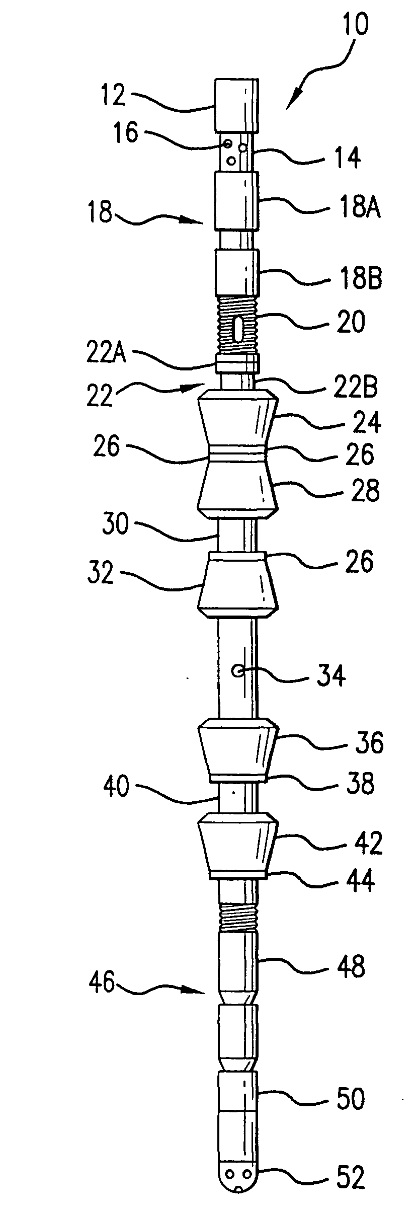
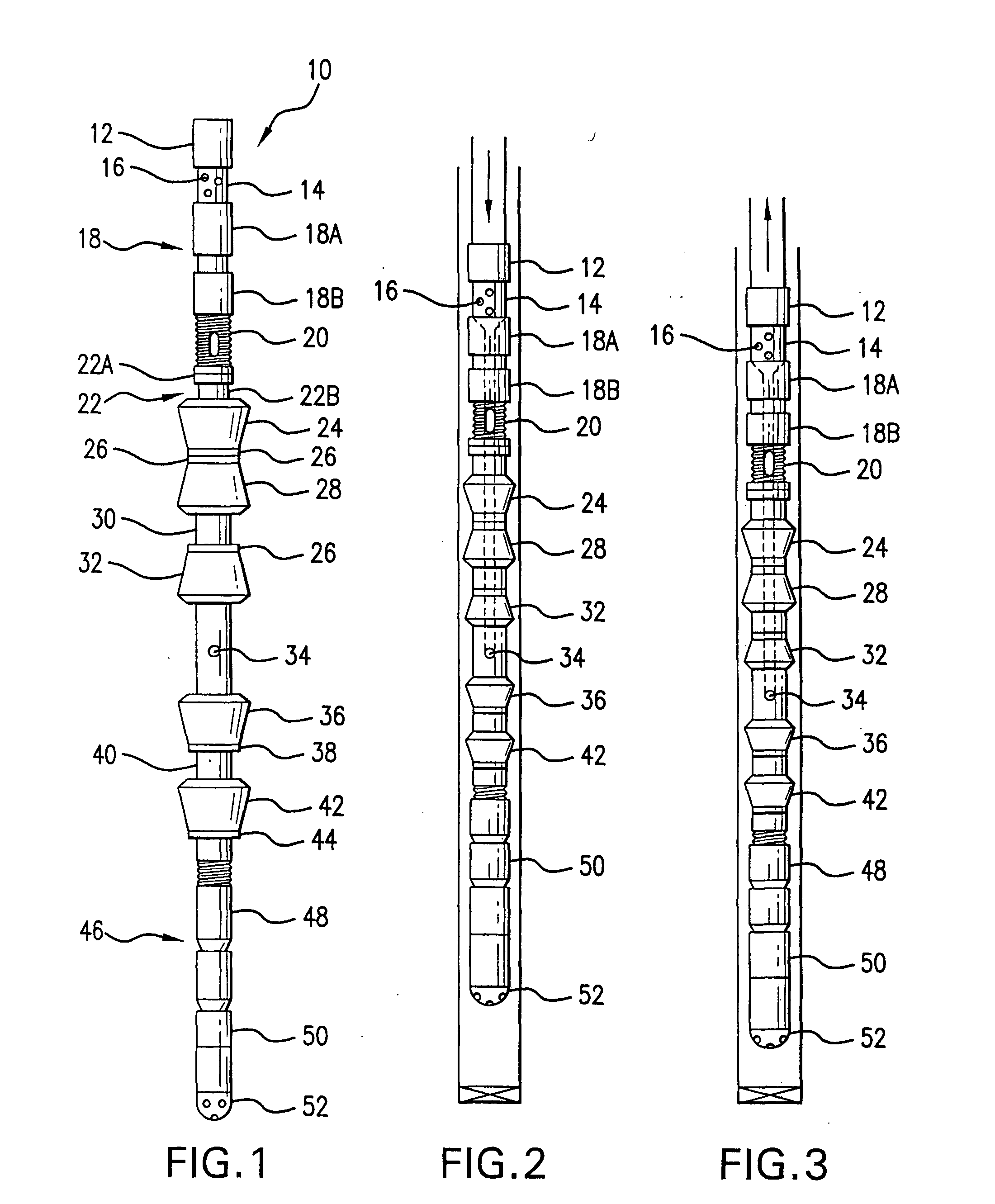
[0110]Following the procedures set forth in Examples 1 and 2, another well was injected with 30 barrels of the emulsion. A surge / pressure wash tool was placed at the end of the tubing string and run into the well. Then an additional 100 barrels of emulsion fluid was allowed to gravity flow into the well through the annulus casing valve. The emulsion followed the wash tool down the well. When the wash tool reached the slotted liner or the perforated zone, the wash tool began to float indicating the well was still plugged. After 15 minutes, the wash tool reached the bottom of the well. Then it was moved up and down the length of the derrick (45 feet) thus promoting a suction in the upward movement of the wash tool, below the wash tool. The tubing string and wash tool on its own weight returned to the bottom of the well with the lowering of the rig's blocks and elevators holding the tubing string. This mov...


PUM


Abstract

A method for cleaning oil wells to increase the flow of oil thereof by use of a unique cleaning emulsion comprising of water, hydrocarbon solvent, terpene hydrocarbon material, demulsifier, detergent, and optionally an acid. This one step method provides for the simultaneously cleaning/removal of asphaltene and/or paraffin and scale at a wide range of temperatures. This method can be used alone or with the assistance of a wash tool which is a combination pressure and surge wash tool having a nipple assembly, or a hydro self-rotating nozzle wash tool.

Description

RELATED PATENT APPLICATIONS[0001]This present pending utility patent application is derived from pending provisional patent application Ser. No. 61 / 465,170 filed on Mar. 15, 2011 and is the priority date for this pending utility patent application.BACKGROUND OF THE INVENTION[0002]1. Field of the Invention[0003]This invention relates to oil and gas production wells and particularly to methods of simultaneously removing asphaltene and / or paraffin and scale from such wells with eco-friendly compositions used under adverse weather conditions.[0004]2. Description of the Prior Art[0005]Paraffin and / or asphaltene and scale formation in producing oil wells, and particularly those wells producing high-paraffin containing oils, significantly interferes with the effectiveness and efficiency of the well production. In severe cases, the presence of paraffin and / or asphaltene and scale, can, in essence, cause the oil production for a given well to cease.[0006]Generally, the paraffin and / or asphal...

Claims


Application Information

Patent Timeline
IPC IPC(8): E21B37/00C09K8/524
CPCE21B37/00C09K8/524E21B37/06
Inventor DYER, RICHARD J.
Owner DYER RICHARD J
Why Eureka
Try Eureka