Anti-slip insert mat and method for producing said insert mat

a technology of insert mats and inserts, which is applied in the direction of floor coverings, monocoque constructions, superstructure sub-units, etc., can solve the problems of hooking islands, requiring a significant amount of effort, and complicated and expensive flocking sub-regions of the free surface of nonwovens, so as to achieve less complex and less expensive. the effect of carrying

Inactive Publication Date: 2012-09-20
IDEAL AUTOMOTIVE BAMBERG
View PDF13 Cites 8 Cited by
  • Summary
  • Abstract
  • Description
  • Claims
  • Application Information

AI Technical Summary

Benefits of technology

[0007]The present invention should also disclose an insert mat and a method for producing the insert mat, which are less expensive, simpler, and less complex to carry out than known insert mats and / or methods.

Problems solved by technology

Flocking subregions of the free surface of the nonwoven is extremely complicated and expensive.
Although an insert mat of this kind can in fact fulfill the currently general requirements with regard to the adhesion force of the insert mat to the floor, i.e. to the cut pile of the carpeted floor pan of the passenger vehicle, this takes a significant amount of effort.
On the other hand, for example due to soiling of the underside of the insert mat, the hooking islands composed of the short, relatively fine fibers from the flocking procedure can over time lose the force of adhesion to the cut pile of the carpeted floor pan of the motor vehicle.
Even if the adhesion islands that are produced by flocking are cleaned at conventional carwashes, for example with two brush rollers, this does not always succeed to a satisfactory degree since the dirt and dust gets trapped rather stubbornly between the fibers of the flocked islands.
Although this single-layer piece of interior carpeting has in fact proven successful, the requirements for adhesiveness of insert mats are always increasing, thus making it necessary to increase the static friction or adhesive force of the insert mat to its underlying support.
The composite material disclosed in this reference also does not fulfill the requirements for a high level of static friction and adhesive force.

Method used


Image

  • Anti-slip insert mat and method for producing said insert mat
  • Anti-slip insert mat and method for producing said insert mat
  • Anti-slip insert mat and method for producing said insert mat

Examples


Embodiment Construction

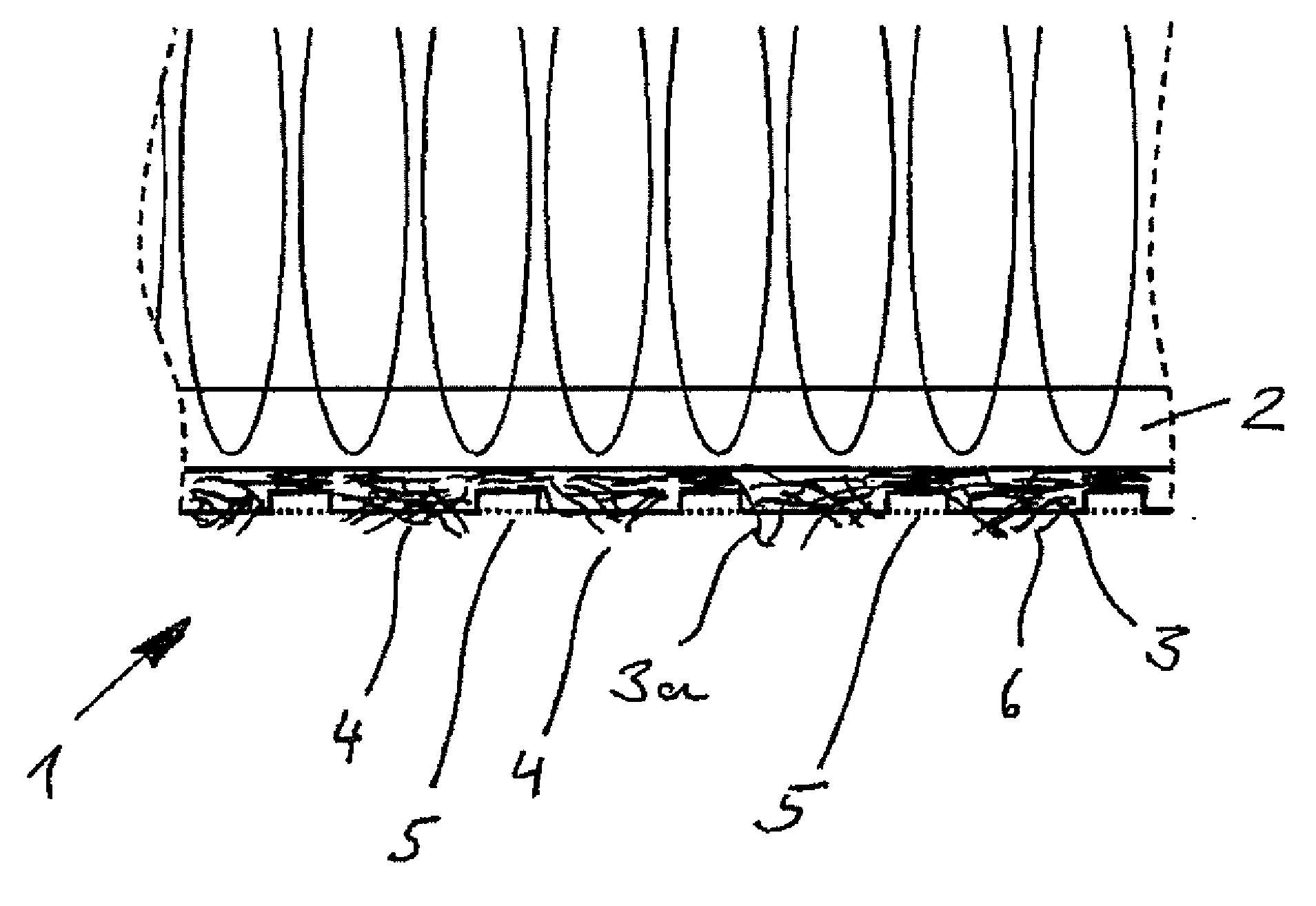
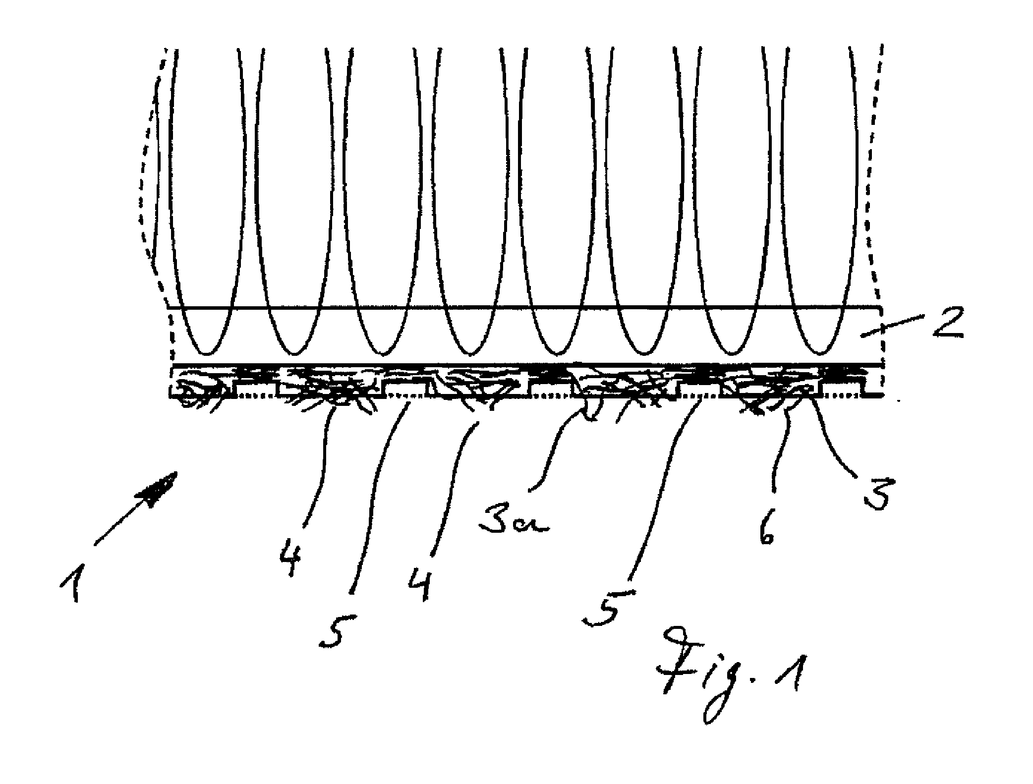
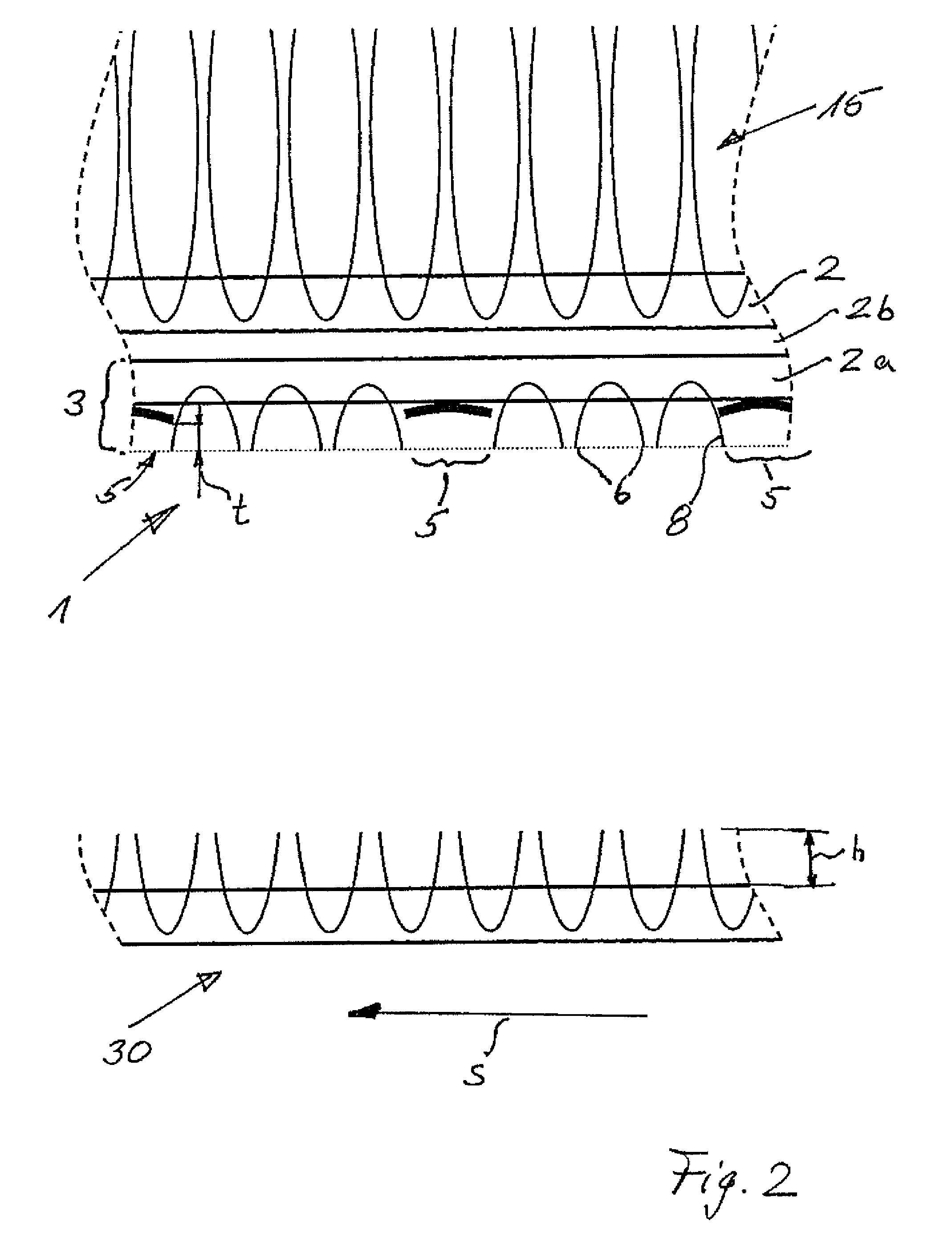
[0037]A first exemplary embodiment of the insert mat 1 according to the invention (FIG. 1) has a primary backing as a backing layer 2 for a decorative layer 15. A hooking layer 3 is attached to the underside of the backing layer 2 by means of a bonding layer (not shown in FIG. 1). The hooking layer 3 is composed of fibers 3a. The hooking layer has raised regions 4 and compacted regions 5. Irregular free ends 6 of the fibers 3a composing the hooking layer 3 protrude in the region of the raised regions 4. In the exemplary embodiment according to the invention shown in FIG. 1, the hooking layer is a velourized needle punched nonwoven with a weight per unit area of approx. 200 g / m2 up to 800 g / m2. The fibers 3a of the velourized needle punched nonwoven have a fineness of 20 dtex to 100 dtex and a cut length of 30 mm to 80 mm. The velourized needle punched nonwoven is preferably clipped, but can also be unclipped when there are reduced requirements with regard to the adhesion force. The ...


PUM

PropertyMeasurementUnit
cut lengthaaaaaaaaaa
heightaaaaaaaaaa

Abstract

The invention relates to an anti-slip insert mat having a carrier layer and a textile catching layer formed of filaments/fibers, wherein the catching layer has raised regions and compressed regions of lower height, wherein the raised regions are formed by free ends of the fibers and the compressed regions of the catching layer are formed by permanently pressing the free ends of the fibers.

Description

FIELD OF THE INVENTION[0001]The invention relates to an anti-slip insert mat and a method for producing said insert mat.BACKGROUND OF THE INVENTION[0002]Known insert mats for inserting into footwells of motor vehicles, in particular passenger vehicles with built-in carpeted floor pans, have essentially the following design.[0003]A use / decorative surface is tufted into a backing layer and in most cases, is embodied as a cut pile surface, i.e. with the tufting loops cut open. A nonwoven is situated on the side of the backing layer oriented away from the decorative side and is bonded to the entire surface of the backing layer. In order to achieve a sufficient adhesion of the insert mat to the carpeted floor pan of the passenger vehicle, it is common for subregions of the free surface of the nonwoven to be flocked with short fibers so as to produce adhesion islands. Flocking subregions of the free surface of the nonwoven is extremely complicated and expensive. For example, after the att...

Claims


Application Information

Patent Timeline
Patent Type & Authority Applications(United States)
IPC IPC(8): B60N3/04D06C15/00D06C7/00D06C13/08D04H1/46
CPCB32B5/26B32B2307/744B32B2471/04B32B2605/08B60N3/048D06N2211/263D02G3/445D04H13/00D06N7/0081D06N2209/106D02G3/38
Inventor RODING, HUBERTFISCHER, BJORN
Owner IDEAL AUTOMOTIVE BAMBERG
Why Eureka
Try Eureka