
Apparatus and methods for phase tuning adjustment of signals

Inactive Publication Date: 2012-09-20
L 3 COMM INTEGRATED SYST
View PDF1 Cites 5 Cited by
  • Summary
  • Abstract
  • Description
  • Claims
  • Application Information

AI Technical Summary

Benefits of technology

[0006]The disclosed apparatus and methods may be employed in a variety of applications, and in one exemplary embodiment may be implemented to correct phase errors by tuning the phase delay of at least one RF sub-assembly such as an individual transmission line of a RF power combiner of a RF distribution network that includes multiple interconnected transmission line sub-assemblies. In such an embodiment, phase delay of one or more of the multiple individual interconnected transmission line sub-assemblies may be varied to reduce a RF signal phase error of the individual transmission line sub-assembly, e.g., such that the combined root mean square (RMS) RF signal phase error of the interconnected sub-assemblies results in an overall phase error that is within the allowable phase tolerance for the system.
[0007]The disclosed apparatus and methods may be implemented in one exemplary embodiment using an apparatus that is relative inexpensive, relatively simple and non-labor intensive to install in a production environment (e.g., for microstrip circuits, stripline circuits, etc.), relatively easy to operate, and that is space efficient. In this regard, space efficiency may be achieved by adjustably varying a spacing between the electrical conductor (e.g., microstrip transmission line or stripline) and an electrically conductive ground plane in a non-inline manner such that the length of the electrical conductor is not affected or required to be longer.
[0008]Examples of other advantages that may be optionally realized in various embodiments of the disclosed apparatus and methods include, but are not limited to, the flexibility to provide for adjustment of a signal phase anywhere on a microstrip or stripline board, the ability to provide for fine tuning of a signal phase by turning a screw or other type of provided adjustable member, the ability to provide for adjustment of a signal phase at multiple places in a design, the ability to provide for increasing the amount of phase tuning by adding more adjustable members (e.g., screws and openings for receiving the same), the ability to provide for phase tuning with relatively small impact on insertion loss and / or on voltage standing wave ratio (VSWR), the ability to provide a signal transmission circuit apparatus that may be made hermetic, e.g., by using a sealant or solder applied to an adjustable member (e.g., screw and nut) after phase adjustment has been made.

Problems solved by technology

In such an embodiment, phase delay of one or more of the multiple individual interconnected transmission line sub-assemblies may be varied to reduce a RF signal phase error of the individual transmission line sub-assembly, e.g., such that the combined root mean square (RMS) RF signal phase error of the interconnected sub-assemblies results in an overall phase error that is within the allowable phase tolerance for the system.

Method used


Image

  • Apparatus and methods for phase tuning adjustment of signals
  • Apparatus and methods for phase tuning adjustment of signals
  • Apparatus and methods for phase tuning adjustment of signals

Examples


example

[0055]The following example is illustrative and should not be construed as limiting the scope of the invention or claims thereof.

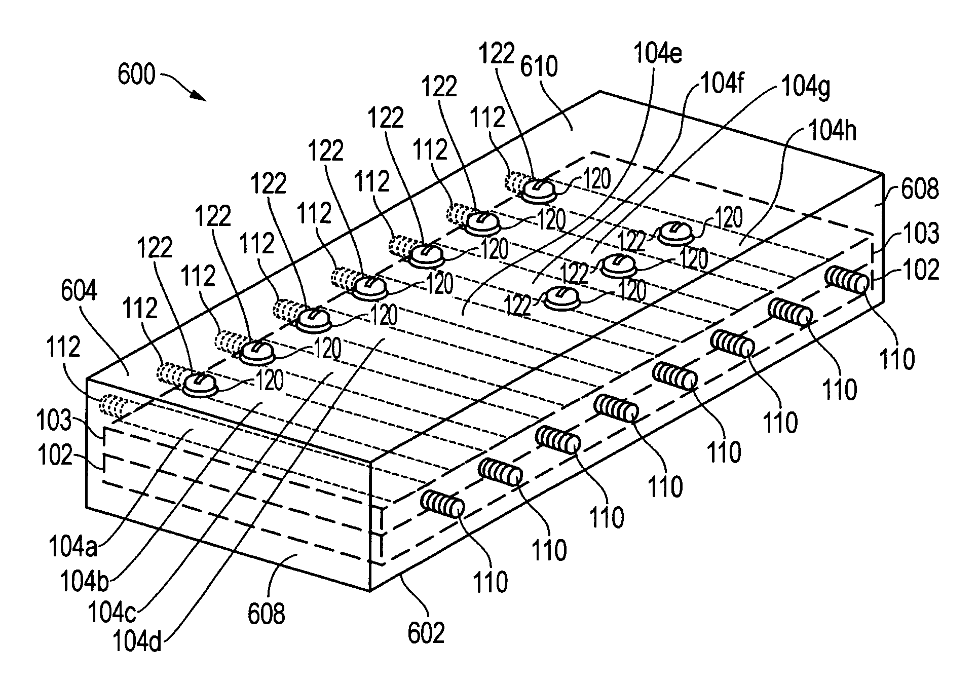
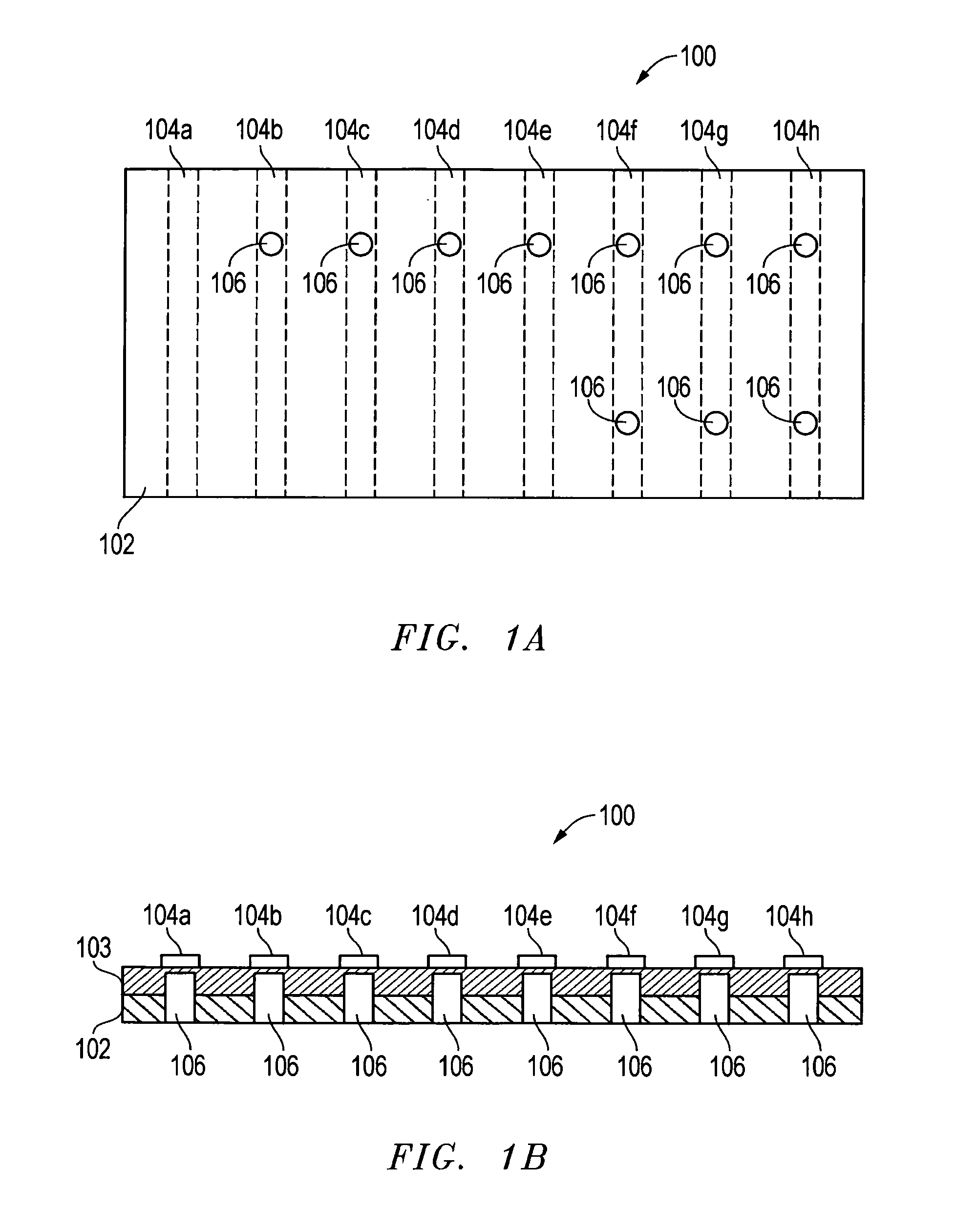
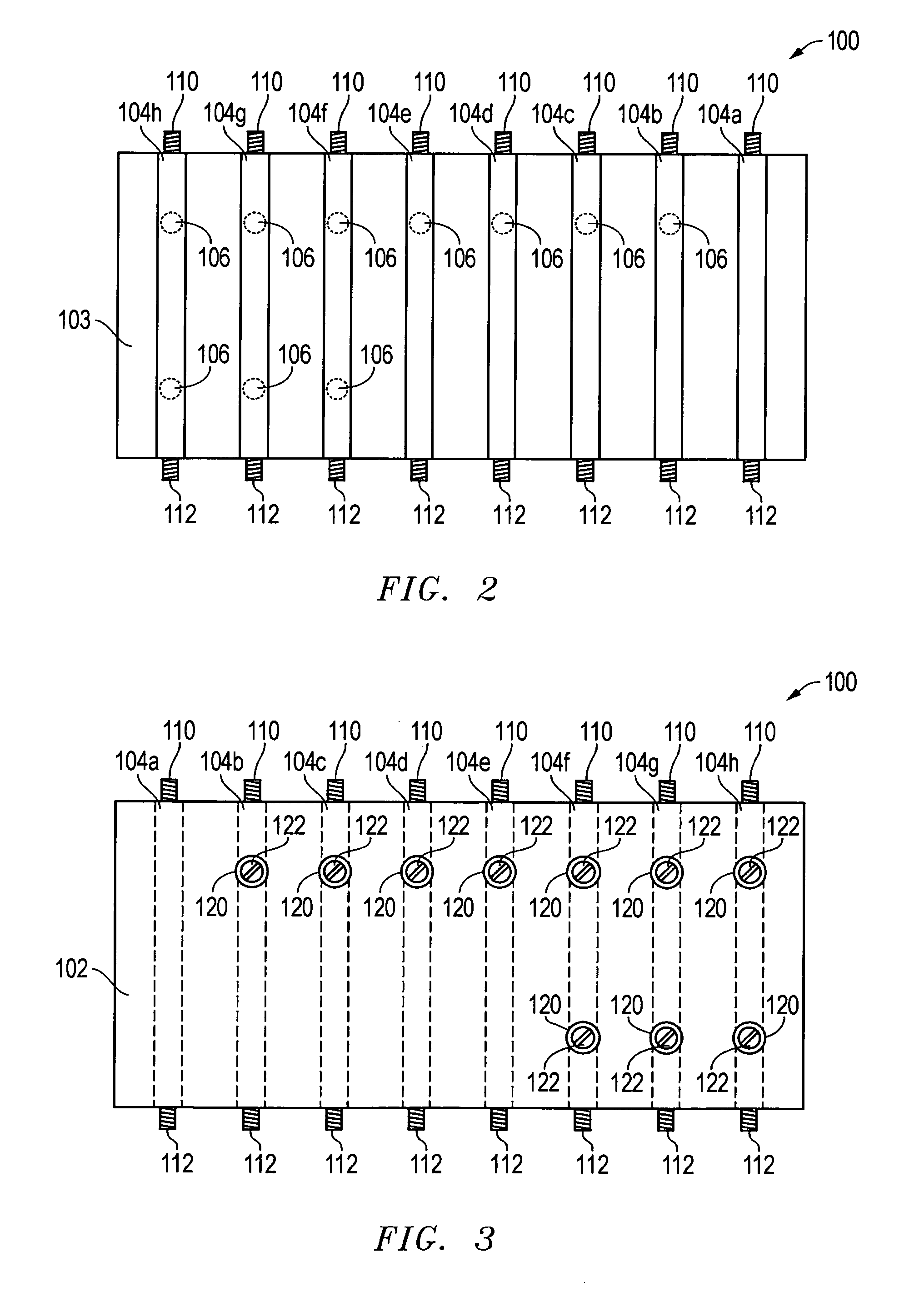
[0056]A prototype board was built on Arlon RF board material (available from Arlon of Rancho Cucamonga, Calif.) using a Protomat X60 (available from LPKF Laser and Electronics of Wilsonville, Oreg.) according to a layout similar to that illustrated in FIGS. 1-4. The dielectric material 103 of the board was 62 mils thick and had 1 ounce copper cladding on the front and back. The dielectric constant of the dielectric material 103 was 2.45. Eight 50 ohm transmission lines 104 were routed into the front copper cladding of the board, with the copper cladding on the back serving as ground plane 102. All lines 104 were of the same width (0.171 inches) and length (3.0 inches). One of the lines 104a was used as a reference with no holes routed adjacent thereto. Two of the lines 104b and 104c each had a single #4 hole 106 routed on the back of the board adjacent eac...


PUM


Abstract

Apparatus and methods for tuning the phase of a signal communicated by an electrical conductor by adjustably varying a spacing between the electrical conductor and at least a portion of an electrically conductive ground plane that is disposed in spaced relationship with the electrical conductor.

Description

[0001]This invention was made with United States Government support under Contract No. FA8620-06-G-4003. The Government has certain rights in this invention.FIELD OF THE INVENTION[0002]This invention relates generally to phase tuning, and more particularly, to phase tuning adjustment.BACKGROUND OF THE INVENTION[0003]Coaxial line stretchers or small wire filaments are conventionally used to tune the phase in a radio frequency (“RF”) sub-assembly such as an individual transmission line of an apparatus such as RF power combiner or RF divider. For example, a power combiner, divider, or boresight RF distribution network may consist of multiple interconnected transmission line sub-assemblies that each has a RF signal phase error. The combined RF signal phase error of the interconnected sub-assemblies may result in an overall phase error that exceeds the allowable phase tolerance for the system, therefore requiring phase tuning of the individual sub-assemblies. However, adjustable coaxial ...

Claims


Application Information

Patent Timeline
IPC IPC(8): H01P5/12
CPCH01P1/184
Inventor HEIN, PAUL W.SAYAVONGSA, VAN V.DOWD, JAMES D.
Owner L 3 COMM INTEGRATED SYST
Learn More