Battery Pack Directed Venting System

a technology of venting system and battery pack, which is applied in the direction of battery/fuel cell control arrangement, battery components, battery/charger components, etc., can solve the problems of thermal runaway of lithium-ion secondary cells, cell chemistries that require special handling during fabrication, and reducing the reaction rate and heat generation. , to achieve the effect of minimizing the effect of thermal runaway

Active Publication Date: 2012-09-20
TESLA INC
View PDF6 Cites 50 Cited by
  • Summary
  • Abstract
  • Description
  • Claims
  • Application Information

AI Technical Summary

Benefits of technology

[0008]The present invention provides a thermal management system for minimizing the effects of thermal runaway occurring within one or more batteries contained within a sealed battery pack, the system including a battery venting assembly integrated into the sealed battery pack. In accordance with the invention, the battery venting assembly is comprised of an exhaust port integrated into an outer wall of the battery pack; a valve retention plate coupled to a surface of the outer battery pack wall, where the valve retention plate covers the exhaust port and includes a plurality of retention plate ports; and a plurality of valves configured to seal the plurality of retention plate ports, where each of the valves seals the corresponding retention plate port during normal operating conditions and unseals the corresponding retention plate port when an excess pressure arises within the battery pack due to one or more of the batteries within the pack entering into thermal runaway. Each valve is preferably fabricated from an elastomeric material, such as fluorosilicone, and preferably has a cracking pressure in the range of 0.5 to 1.0 psi. The sealed battery pack may be divided into a plurality of compartments, for example using a central battery pack member and a plurality of cross-members, where the battery venting assembly is integrated into one of the plurality of sealed battery pack compartments.

Problems solved by technology

Among rechargeable batteries, also referred to as secondary batteries, one of the primary disadvantages is their relative instability, often resulting in these cells requiring special handling during fabrication, storage and use.
Additionally, some cell chemistries, for example lithium-ion secondary cells, tend to be more prone to thermal runaway than other primary and secondary cell chemistries.
Thermal runaway occurs when the internal reaction rate of a battery increases to the point that more heat is being generated than can be withdrawn, leading to a further increase in both reaction rate and heat generation.
Thermal runaway may be initiated by a short circuit within the cell, improper cell use, physical abuse, manufacturing defects, or exposure of the cell to extreme external temperatures.
During the initial stages of a thermal runaway event, the cell undergoing runaway becomes increasingly hot due to the increased reaction rate and the inability of the system to withdraw the heat at a rapid enough rate.
While the safety pressure release vent built into many cells may help to release some of the gas generated by the reaction, eventually the increased temperature in concert with the increased internal cell pressure will lead to the formation of perforations in the cell casing.
Once the cell casing is perforated, the elevated internal cell pressure will cause additional hot gas to be directed to this location, further compromising the cell at this and adjoining locations.
While the increase in cell temperature during a thermal runaway event is sufficient to damage materials in proximity to the event and to lead to the propagation of the event to adjoining cells, it is not until the hot gas escapes the confines of the cell, and potentially the confines of the battery pack, that the risk to people and property damage is significant.
However, once this gas exits the confines of the cell / battery pack and comes into contact with the oxygen contained in the ambient atmosphere, the AIT of these same materials will decrease significantly, potentially leading to their spontaneous combustion.
It is at this point in the event cycle that extensive collateral property damage is likely to occur and, more importantly, that the risks to the vehicle's passengers leaving the vehicle, or to first responders attempting to control the event, becomes quite significant.

Method used


Image

  • Battery Pack Directed Venting System
  • Battery Pack Directed Venting System
  • Battery Pack Directed Venting System

Examples


Embodiment Construction

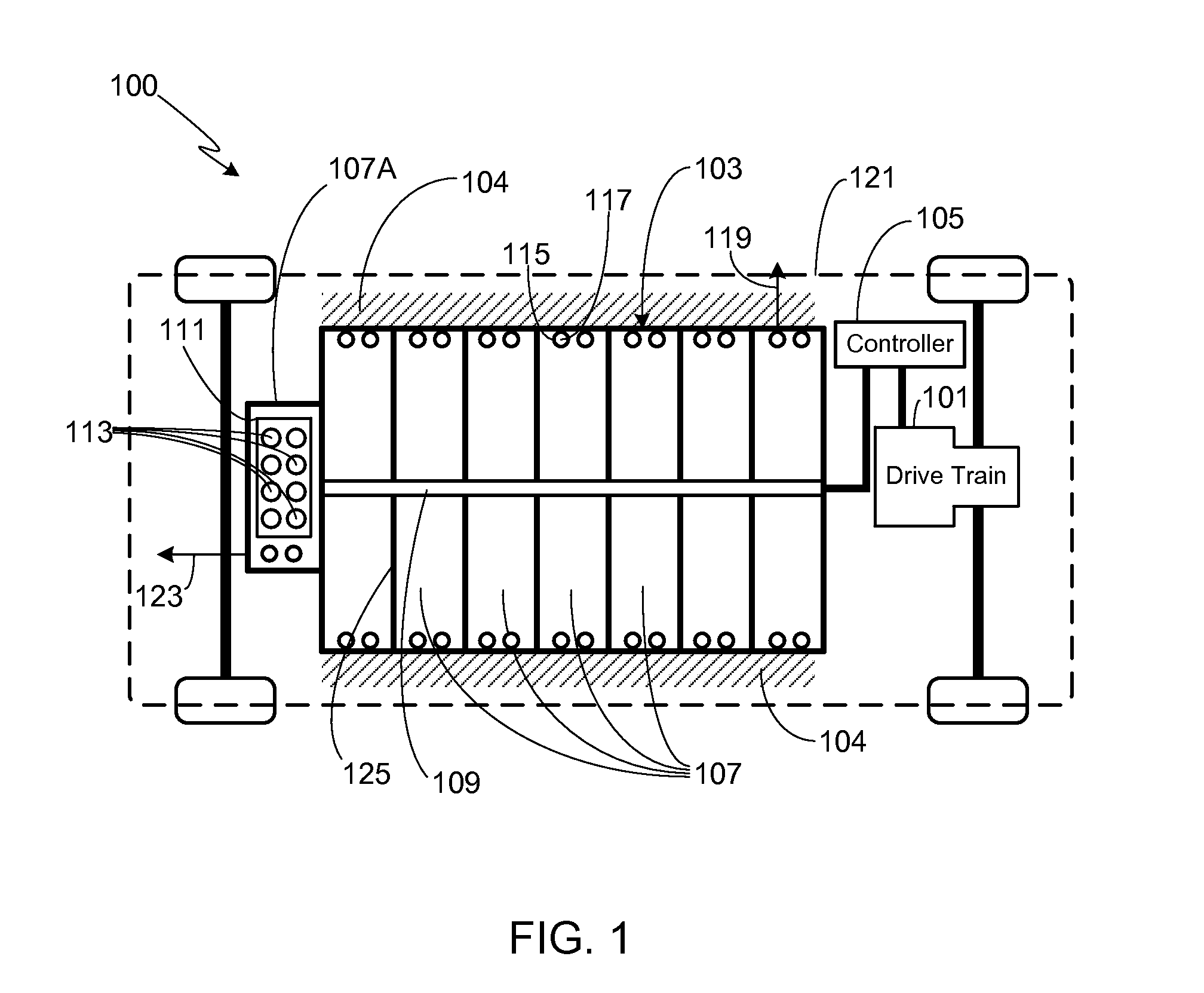
[0032]In the following text, the terms “battery”, “cell”, and “battery cell” may be used interchangeably and may refer to any of a variety of different cell types, chemistries and configurations including, but not limited to, lithium ion (e.g., lithium iron phosphate, lithium cobalt oxide, other lithium metal oxides, etc.), lithium ion polymer, nickel metal hydride, nickel cadmium, nickel hydrogen, nickel zinc, silver zinc, or other battery type / configuration. The term “battery pack” as used herein refers to multiple individual batteries contained within a single piece or multi-piece housing, the individual batteries electrically interconnected to achieve the desired voltage and capacity for a particular application. The term “electric vehicle” as used herein may refer to an all-electric vehicle, also referred to as an EV, a plug-in hybrid vehicle, also referred to as a PHEV, or a non-plug-in hybrid vehicle, also referred to as a HEV, where a hybrid vehicle utilizes multiple propuls...


PUM

PropertyMeasurementUnit
angleaaaaaaaaaa
angleaaaaaaaaaa
angleaaaaaaaaaa

Abstract

A thermal management system is provided that minimizes the effects of thermal runaway within a battery pack, the system using an integrated battery venting assembly comprised of an integrated exhaust port, a valve retention plate that covers the exhaust port and includes a plurality of retention plate ports, and a plurality of valves that are configured to seal the retention plate ports under normal conditions and unseal the retention plate ports during thermal runaway. As hot gas passes through the retention plate ports, the plate is configured to melt and be ejected, thereby allowing subsequent hot gas to pass through the larger exhaust port. A perforated cover plate may be used to protect the external surfaces of the retention plate and valves. An internally mounted exhaust guide may be used to direct the flow of hot gas expelled during the thermal runaway event.

Description

CROSS-REFERENCE TO RELATED APPLICATION[0001]This application is a continuation-in-part of U.S. patent application Ser. No. 13 / 475,955, filed 19 May 2012, which is a continuation-in-part of U.S. patent application Ser. No. 13 / 076,003, filed 30 Mar. 2011, which is a continuation-in-part of U.S. patent application Ser. No. 12 / 798,198, filed 30 Mar. 2010, which is a continuation-in-part of U.S. patent application Ser. No. 12 / 386,684, filed 22 Apr. 2009, the disclosures of which are incorporated herein by reference for any and all purposes. U.S. patent application Ser. No. 13 / 076,003, filed 30 Mar. 2011, claims the benefit of the filing date of U.S. Provisional Patent Application Ser. No. 61 / 426,254, filed 22 Dec. 2010, the disclosure of which is incorporated herein by reference for any and all purposes.FIELD OF THE INVENTION[0002]The present invention relates generally to batteries and, more particularly, to means for mitigating the effects and hazards associated with a battery undergoi...

Claims


Application Information

Patent Timeline
Patent Type & Authority Applications(United States)
IPC IPC(8): H01M10/50H01M2/12H01M50/213H01M50/262H01M50/358H01M50/367
CPCB60L3/0046Y02T10/7061B60L11/1864B60L11/1874B60L11/1877B60L11/1879B60L2240/545H01M2/1077H01M2/1094H01M2/1235H01M2/1252H01M2/127H01M10/0525H01M10/5016H01M10/504H01M10/5044H01M10/5057H01M10/5087H01M2200/10Y02T10/7005Y02T10/7011B60L11/1803H01M10/625H01M10/653H01M10/6556H01M10/655H01M10/658B60L50/51B60L58/21B60L58/26B60L50/66B60L50/64B60L58/18Y02E60/10Y02T10/70H01M50/24H01M50/342H01M50/383H01M50/394H01M50/367H01M50/213H01M50/358H01M50/262
Inventor MARDALL, JOSEPHHERRON, NICHOLAS HAYDENGRACE, DUSTINHERMANN, WESTON ARTHURWEINTRAUB, JEFFREY C.PINKLEY, GARY ALLEN
Owner TESLA INC
Why Eureka
Try Eureka