Vehicle light

a technology for vehicles and headlamps, applied in vehicle headlamps, transportation and packaging, lighting and heating equipment, etc., can solve the problem of increasing the dimension of vehicle lights b>200/b> in an optical axis direction accordingly

Inactive Publication Date: 2012-09-27
STANLEY ELECTRIC CO LTD
View PDF22 Cites 33 Cited by
  • Summary
  • Abstract
  • Description
  • Claims
  • Application Information

AI Technical Summary

Benefits of technology

[0046]According to the fifteenth aspect of the present invention, a high-luminance light-emitting part can be constructed which is even smalle...

Problems solved by technology

However, since the vehicle light described in Patent Literature 1 is constructed such that the laser light source 210 and the phosphor 220 are arranged physically...

Method used


Image

  • Vehicle light
  • Vehicle light
  • Vehicle light

Examples


first embodiment

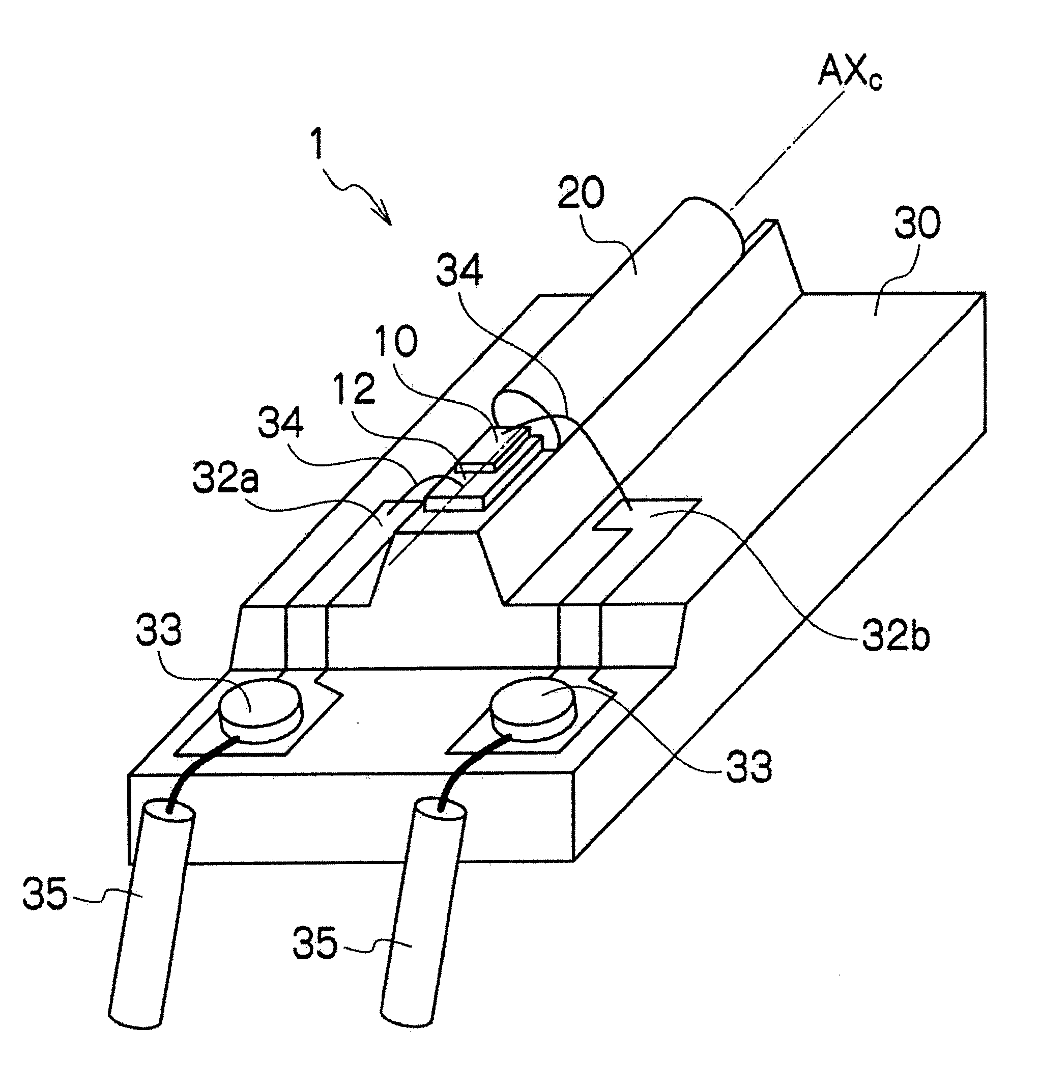
[0071]FIG. 4 is a perspective view showing a construction of the laser light source device 1 according to the first embodiment of the present invention, and FIGS. 5A and 5B are, respectively, a perspective view and a top view showing a construction of a wavelength converting structure 20 comprising the light source device 1. FIGS. 6A and 6B are, respectively, sectional views taken along line 6a-6a and line 6b-6b in FIG. 5B.

[0072]A laser diode 10 as a laser light source is a semiconductor laser which, for example, includes a nitride-based semiconductor layer such as GaN and which radiates a blue light with a wavelength of around 450 nm. The laser diode 10 is mounted on a submount 12 made of ceramics or the like. The submount 12 on which the laser diode 10 is mounted is, in turn, mounted on an upper surface of a heat sink stand 30. A conductor wiring (not shown) that is electrically connected to a back electrode of the laser diode 10 is formed on a surface of the submount 12. The cond...

second embodiment

[0111]Next, a laser light source device 2 according to a second embodiment of the present invention will be described.

[0112]FIG. 10A is a sectional view showing a construction of a wavelength converting structure 20a according to the second embodiment of the present invention. The laser light source device 2 (the wavelength converting structure 20a) according to the present embodiment is similar to the wavelength converting structure 20 according to the first embodiment described above with the exception of a polarizing filter 40 for blocking returning light to a laser diode 10 being provided adjacent to a laser incident end surface 23 of a light-guiding part 22.

[0113]The polarizing filter 40 is a filter for transmitting a laser beam which is outputted from the laser diode 10 and introduced into the light-guiding part 22 from the laser incident end surface 23. As shown in FIG. 10A, the polarizing filter 40 is arranged between the laser diode 10 and the laser incident end surface 23....

third embodiment

[0115]Next, a laser light source device 3 according to a third embodiment of the present invention will be described.

[0116]FIG. 10B is a sectional view showing a construction of a wavelength converting structure 20b with an improved returning light blocking function and improved transmittance of laser beams directed toward a light-guiding part 22. The laser light source device 3 (the wavelength converting structure 20b) according to the present embodiment is similar to the wavelength converting structure 20a according to the second embodiment described above with the exception of an antireflective film 50 provided adjacent to a polarizing filter 40.

[0117]As shown in FIG. 10B, the antireflective film 50 is arranged between a laser diode 10 and the polarizing filter 40. The antireflective film 50 is configured by alternately and repetitively laminating two types of layers with different refractive indexes. By setting a layer thickness of each layer in accordance with a wavelength of a...


PUM


Abstract

A vehicle light which uses a laser light source device and has a shorter dimension in an optical axis direction than conventional vehicle lights. The vehicle light comprises a laser light source device and an optical system configured so as to form a predetermined light distribution pattern. The laser light source device includes: a cylindrical light-guiding part having a diffusing surface set in a region other than a light-introducing surface; a phosphor arranged in a light-emitting region on an outer circumferential surface of the light-guiding part; a reflective film arranged in a region of the light-guiding part other than the light-introducing surface and the light-emitting region; and a laser light source that outputs a laser beam which is introduced into the light-guiding part from the light-introducing surface and enters the phosphor. The light-guiding part and the laser light source are arranged adjacent to each other.

Description

BACKGROUND OF THE INVENTION[0001]1. Field of the Invention[0002]The present invention relates to a vehicle light using a laser light source device and, in particular, to a vehicle light with a shorter dimension in an optical axis direction than conventional vehicle lights.[0003]2. Description of the Related Art[0004]Conventionally, in the field of vehicle lights, there have been demands for a high-luminance light source for illuminating the distance during nighttime by a light with sufficient intensity. To meet such demands, a vehicle light has been proposed (for example, refer to Japanese Patent Kokai No. 2010-232044: Patent Literature 1) which uses a laser light source device combining a laser light source with a phosphor (for example, a YAG phosphor) that emits light upon being excited by a laser beam (for example, a blue laser beam).[0005]As shown in FIGS. 1 and 2, a vehicle light 200 described in Patent Literature 1 comprises a laser light source 210, a phosphor 220 that emits ...

Claims


Application Information

Patent Timeline
IPC IPC(8): F21V9/00F21V9/14
CPCF21V9/00F21S48/1241F21S48/1145F21V9/14F21S41/14F21S41/16F21S41/176F21S41/24
Inventor KOIKE, TERUOLIANG, JI-HAO
Owner STANLEY ELECTRIC CO LTD
Why Eureka
Try Eureka