Dual injection points in sagd

a technology of sagd and injection point, which is applied in the direction of fluid removal, earth-moving drilling, borehole/well accessories, etc., can solve the problems of inability to pump out of the ground, difficult production of heavy oil and bitumen from subsurface reservoirs, and inability to achieve greater depths. economical access, increase the effect of sagd efficiency and delay of production

Active Publication Date: 2012-10-04
CONOCOPHILLIPS CO
View PDF9 Cites 28 Cited by
  • Summary
  • Abstract
  • Description
  • Claims
  • Application Information

AI Technical Summary

Benefits of technology

[0015]The invention generally relates to a method to increase the efficiency of SAGD using two injections points, rather than the typical single injection point, and thus avoids introducing new problems, such as solvent reflux, gas breakthrough, delayed production, and

Problems solved by technology

Production of heavy oil and bitumen from a subsurface reservoir can be quite challenging.
Because of this high viscosity oil cannot be pumped out of the ground using typical methods, and it often must be mined or processed in situ.
Greater depths are not economical to access and most reserves are not accessible by the method.
As an in situ recovery process, SAGD requires on-site steam generation and water treatment, translating into expensive surface facilities.
Since steam-to-oil ratios are high and natural gas is often used to generate steam, SAGD is expensive to operate.
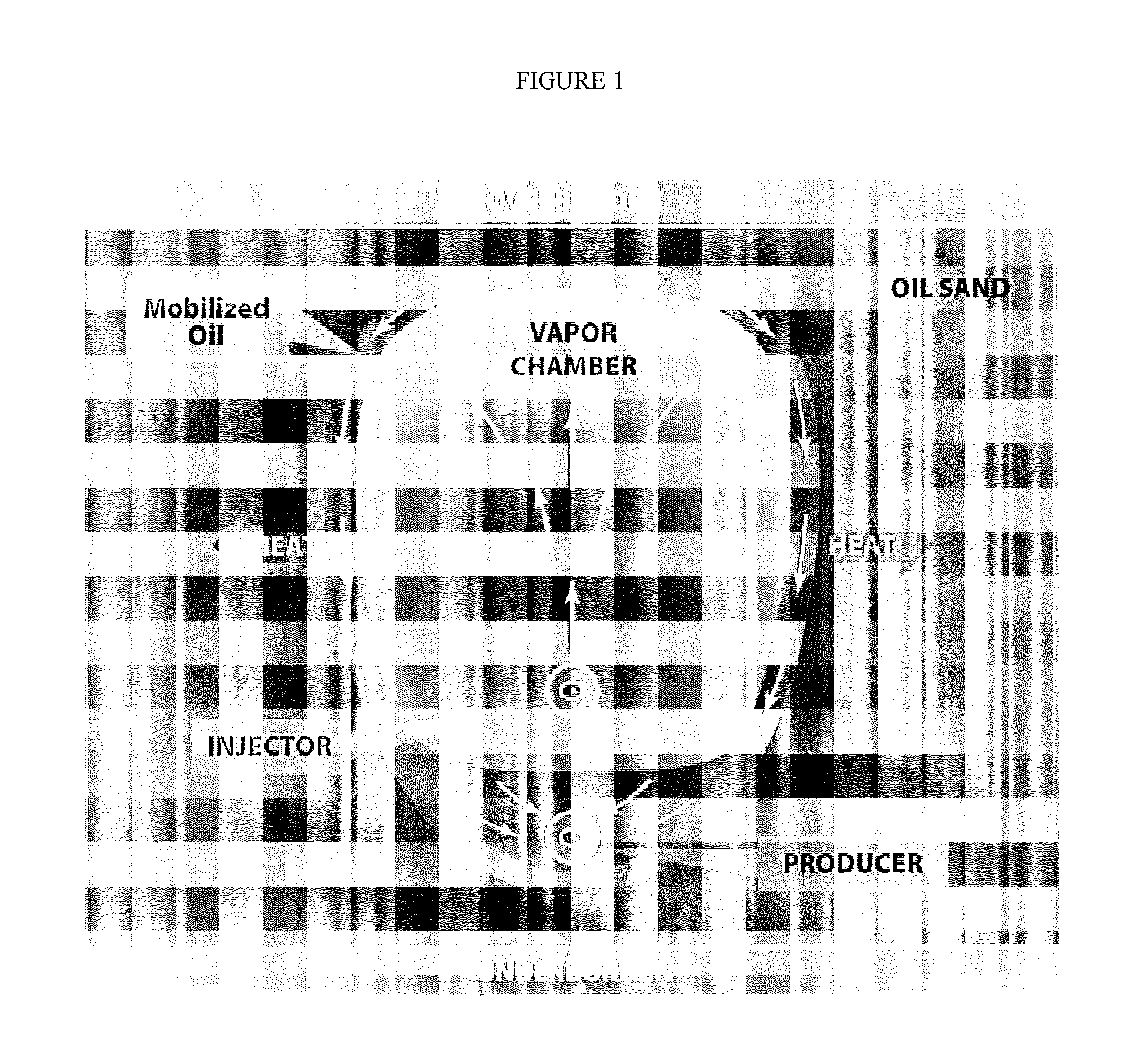
SAGD is very energy intensive largely because the reservoir rock and fluids must be heated enough to lower viscosity and mobilize the petroleum, and heat is lost to overburden and underburden, water and gas intervals

Method used


Image

  • Dual injection points in sagd
  • Dual injection points in sagd
  • Dual injection points in sagd

Examples


example 1

SAGD with Dual Injection Wells

[0052]By using a first injection well placed 5 meters above the production well, and a second injection well placed at least 5 meters above the first injection well, the system of wells performed significantly better than to a single injection well set up.

The second injection well can be placed at any height above the first injection well, as long as it is below the top of the formation. In one embodiment the second injection well is 10 to 15 meters above the first injection well. It is important to note that the injection wells and the production wells can be offset or non-aligned, as known by one skilled in the art.

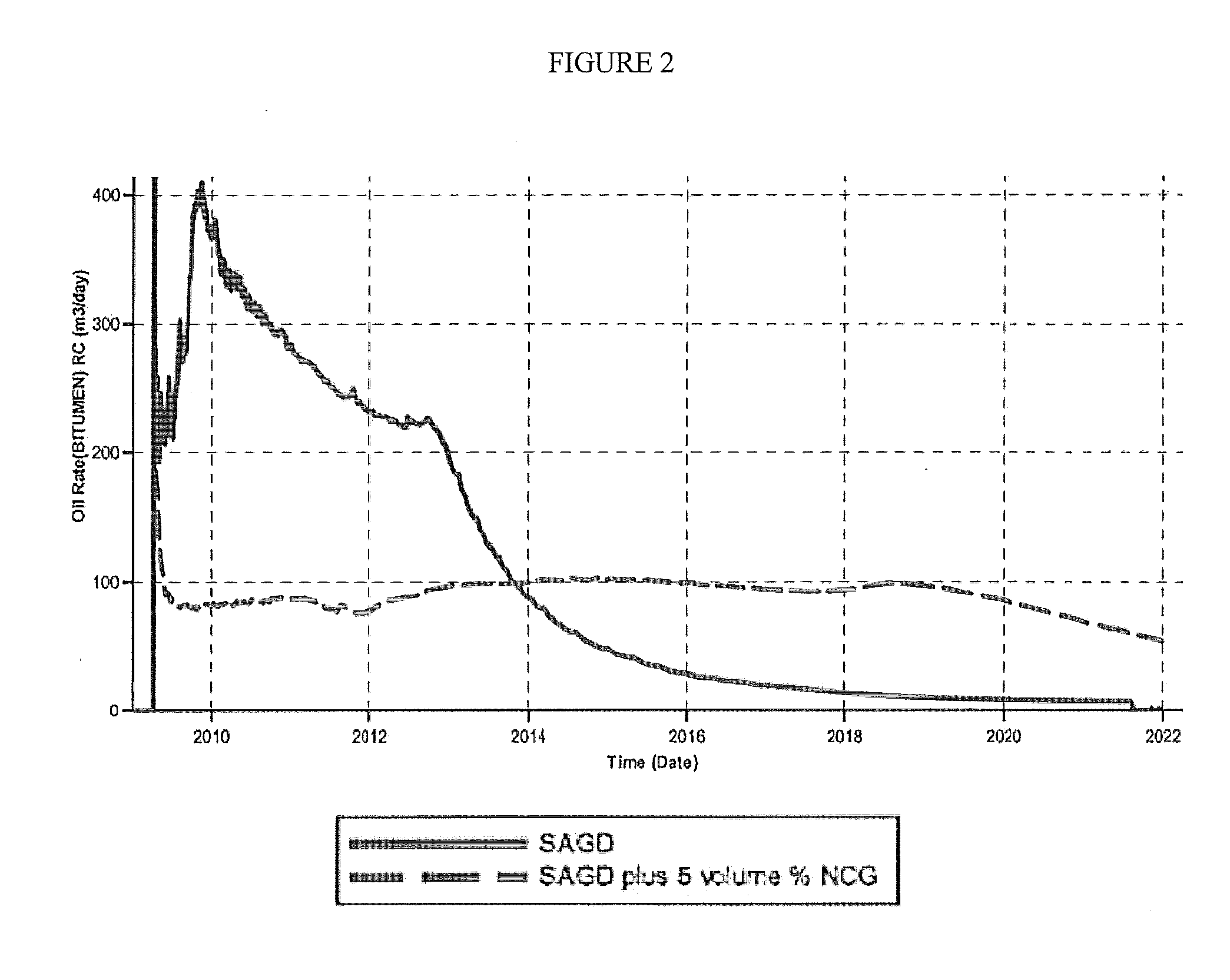
[0053]FIG. 6 plots rate of oil production. The average rate is improved over the base SAGD NCG co-injection case when dual injection strategy is employed.

[0054]A significant improvement in energy efficiency is shown through an improved cSOR (FIG. 7). In this set of simulations, SAGD at 4 MPa shows an improvement of >15%. FIG. 7 also demonst...

example 2

SAGD with Multilateral Injection Wells

[0055]The injection wells can comprise a multilateral well, where the injection wells have a common vertical well bore with a first lateral placed 5 meters above the production well, and a second lateral placed at least 5 meters above the first lateral. It is important to note that the injection wells and the production wells can be offset or non-aligned, as known by one skilled in the art. This dual injector SAGD method concept substantially decreases gas reflux and allows the fluids to move into the production well instead. This movement, in turn, allows the chamber to develop into a classical SAGD shape, retaining the height and oil rate at higher levels while improving the thermal efficiency. Unlike previously reported methods, the shape of the steam chamber is no longer affected by refluxing NCG at the injection well (FIG. 8). Work was carried out using a numerical simulator (CMG STARS) to evaluate the potential benefits of using dual injec...


PUM


Abstract

A method for recovering petroleum from a formation, wherein at least two injection wells and at least one production well are in fluid communication with said formation, comprising: introducing a gaseous mixture into a first and a second injection well at a temperature and a pressure, wherein said gaseous mixture comprises steam and non-condensable gas (NCG); and recovering a fluid comprising petroleum from said production well, wherein said injection wells and a production well are horizontal wells, and wherein said first injection well is disposed 1-10 meters above said production well, and said second injection well is disposed at least 5 meters above said first injection well.

Description

CROSS-REFERENCE TO RELATED APPLICATIONS[0001]This application is a non-provisional application which claims the benefit of and priority to U.S. Provisional Application Ser. No. 61 / 468,731 filed Mar. 29, 2011, entitled “Dual Injection Points in SAGD,” which is hereby incorporated by reference in its entirety.FEDERALLY SPONSORED RESEARCH STATEMENT[0002]Not applicable.FIELD OF THE INVENTION[0003]The invention relates to petroleum production, in particular to an in situ processing method for heavy oil and / or bitumen production.BACKGROUND OF THE INVENTION[0004]Production of heavy oil and bitumen from a subsurface reservoir can be quite challenging. Initial viscosity of the oil at reservoir temperature is often greater than a million centipoise (cP). Because of this high viscosity oil cannot be pumped out of the ground using typical methods, and it often must be mined or processed in situ. Surface mining is limited to reservoirs to a depth of about 70 meters. Greater depths are not econom...

Claims


Application Information

Patent Timeline
IPC IPC(8): E21B43/24
CPCE21B43/2406
Inventor WHEELER, THOMAS J.BROWN, DAVID A.NASR, TAWFIK N.
Owner CONOCOPHILLIPS CO
Why Eureka
Try Eureka