Supercharge Your Innovation With Domain-Expert AI Agents!

Vitreous silica crucible

Active Publication Date: 2012-10-18
SUMCO CORP
View PDF3 Cites 2 Cited by
  • Summary
  • Abstract
  • Description
  • Claims
  • Application Information

AI Technical Summary

Benefits of technology

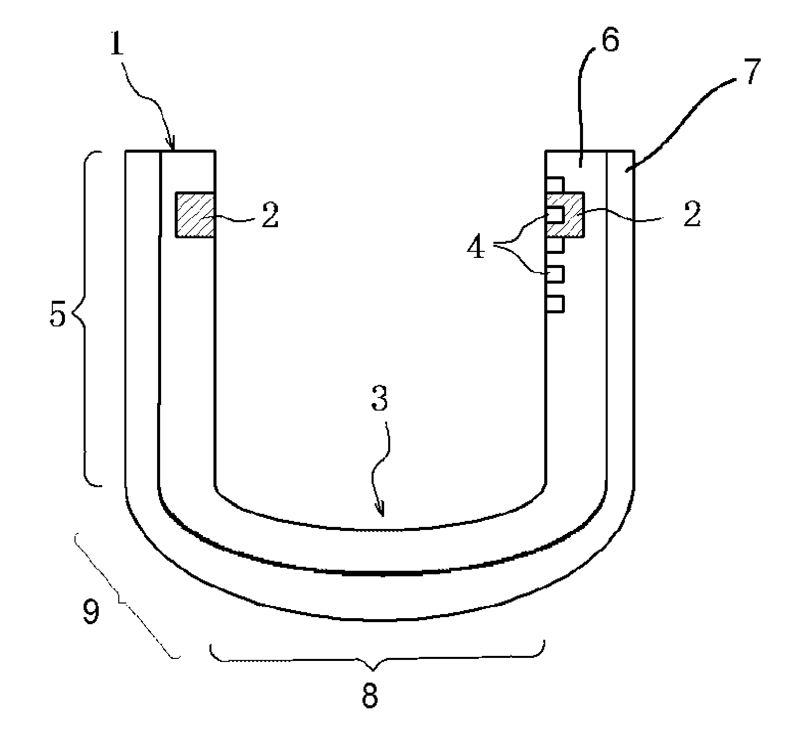
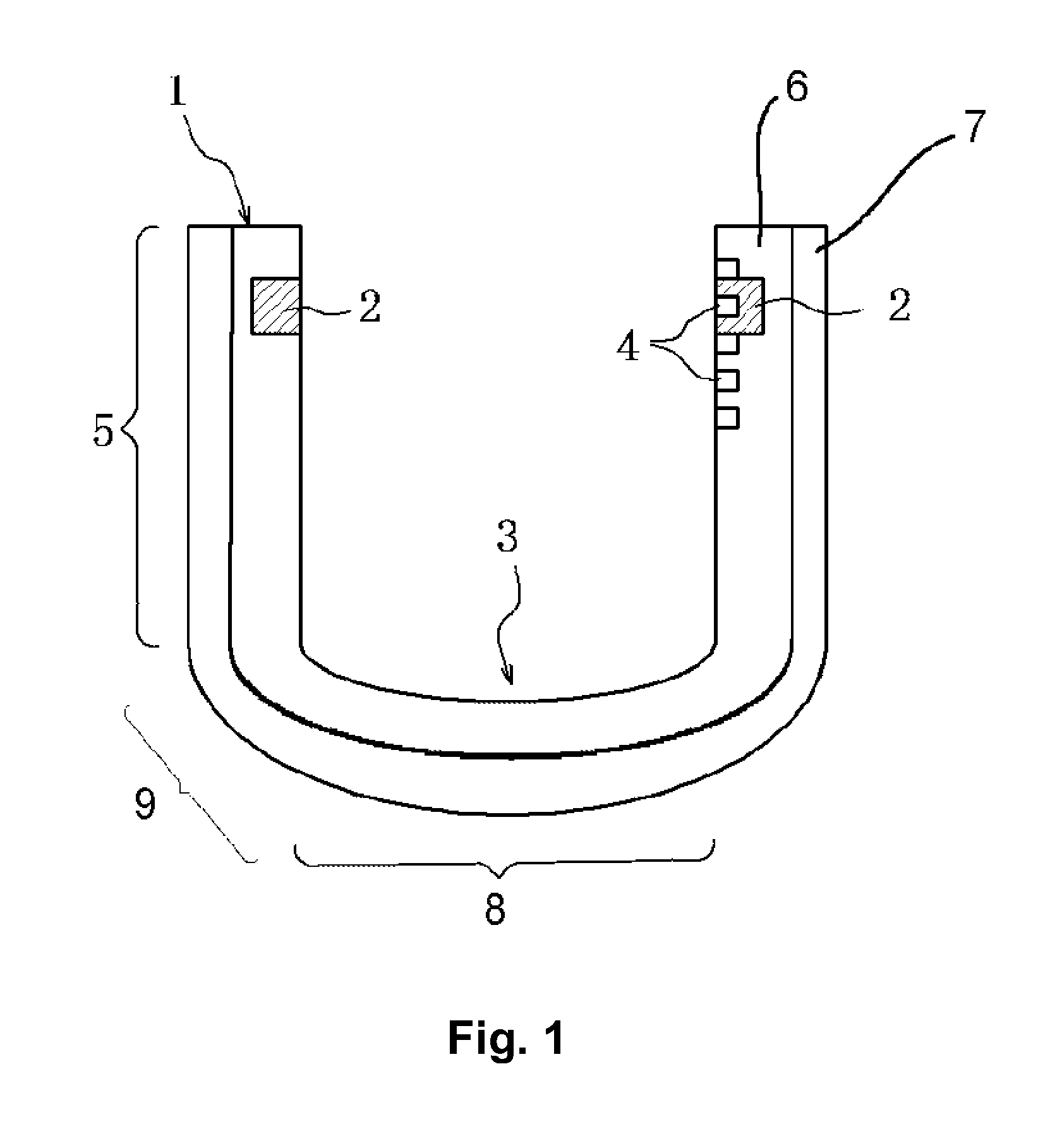
[0020]According to the present disclosure, for example, although the vitreous silica crucible is deformed due to the mass of silicon melt during pulling of a silicon single crystal, a change in position of the melt surface with respect to a position of the special region can be accurately detected. Therefore, directly after the melt surface has passed the special region for preventing vibration of the melt surface, it becomes possible to increase the pulling rate of silicon single crystal, thereby contributing to the enhancement of productivity.

Problems solved by technology

Micro defects are advantageous for capturing heavy metal pollution that occurs in a device process, but may become a source of device failure.
It is general practice to directly observe and monitor the changing level of the melt surface, but such direct observation has the problem in that the decrease in volume of the silicon melt cannot be accurately measured.
The large diameter of the silicon single crystal ingot is problematic in that the phenomenon can easily occur in which the melt surface of the silicon melt sloshes (vibrates) between a portion where a neck part is formed and a portion where a shoulder part is formed, for a duration of a few minutes to a few hours.
However, a method of completely preventing the vibration of the melt surface under any pulling condition has not yet been found.
Therefore, although a distance between an initial melt surface level and a melt surface level changed during pulling is known, a relative position between the melt surface and the special region provided in the vitreous silica crucible cannot accurately be known.
That is, for example, although the sloshing of the melt surface disappears, and the seed crystal arrives at a region beyond the special region and may increase the pulling rate of a silicon single crystal, it may not be determined whether the sloshing disappears due to an effect of the special region or whether a region is one which may increase the pulling rate, and in a real process, it is problematic that the pulling rate of silicon single crystal may not be increased.

Method used


Image

  • Vitreous silica crucible
  • Vitreous silica crucible

Examples


example 1

[0056]A marking in accordance with Example 1 was formed in the following sequence in a vitreous silica crucible of about 800 mm in diameter, which was manufactured by a conventional well known method. The formed marking was a pointed shape of which the diameter is 1 mm. Also, in the present Example, a special region primarily made of natural silica (natural silica / synthetic silica=2 / 1) and having a width of 30 mm in the height direction and a depth of 100 μm was formed in the vitreous silica crucible.

[0057][Laser Marking Sequence]

1. Process of loading a crucible on a bottom plate having an opening for marking at a center thereof with a three-jaw scroll chuck tool for determining a central position of the crucible such that the opening of the crucible is directed downward.

2. Process of determining the central position of the crucible with the three-jaw scroll chuck tool.

3. Process of elevating a laser processor to an inner wall of the crucible.

4. Process of controlling a distance bet...

example 2

[0061]Next, the crucible used in Example 1 was heated to 1400 deg. C. to intentionally deform the crucible. When the laser marking was formed in accordance with Example 1, the special region primarily made of natural silica was visually observed accurately even when the crucible was deformed.

example 3

[0062]The crucible used in Example 1 was loaded on a carbon susceptor having a spacing of about 7 mm at a corner portion, about 80 kg polycrystalline silicon was put in the crucible, the crucible was installed in a CZ furnace, the polycrystalline silicon in the crucible was molten at about 1450 deg. C. and maintained for 20 hours. The special region was visually observed from an exterior of the CZ furnace, and the special region primarily made of natural silica was visually observed accurately. After the crucible was cooled to room temperature, the spacing between the vitreous silica crucible and the carbon susceptor as measured was 2 mm, indicating a large deformation of the crucible. That is, even though the corner portion of the crucible was deformed by about 5 mm, the special region primarily made of natural silica in the vitreous silica crucible having the marking formed in accordance with Example 1 was observed accurately.


PUM

PropertyMeasurementUnit
widthaaaaaaaaaa
widthaaaaaaaaaa
diameteraaaaaaaaaa

Abstract

Provided is a vitreous silica crucible which has a special region for suppressing vibration of melt surface during pulling of a silicon single crystal and at the same time, a marking capable of accurately monitoring a changed position of the melt surface when passing through the special region. The special region for preventing sloshing of silicon melt is provided on an inner wall of a straight body portion, and the marking is provided at least at an upper end and a lower end of the special region.

Description

TECHNICAL FIELD[0001]The present invention relates to a vitreous silica crucible for pulling of silicon single crystals.BACKGROUND ART[0002]In the manufacturing of semiconductor devices, etc. used in electronics technologies leading information-oriented society, silicon wafers may not be omitted. Characteristics of silicon wafers include micro defects such as oxygen precipitate, dislocation, oxygen stacking faults and the like. Micro defects are advantageous for capturing heavy metal pollution that occurs in a device process, but may become a source of device failure. Therefore, there may be a need to adjust the oxygen concentration in a crystal to a predetermined concentration corresponding to types of devices or device processes used.[0003]As a current method of manufacturing silicon single crystals, the “Czochralski method” (hereinafter referred to as “CZ method”) of manufacturing silicon single crystals through pulling is generally used. In addition, there is a method called the...

Claims


Application Information

Patent Timeline
Patent Type & Authority Applications(United States)
IPC IPC(8): C30B15/10
CPCC03C19/00C03C23/0025Y10T117/1032C30B35/002C30B15/10C03B20/00C30B29/06
Inventor SUDO, TOSHIAKIKISHI, HIROSHIKODAMA, MAKIKO
Owner SUMCO CORP
Features
  • R&D
  • Intellectual Property
  • Life Sciences
  • Materials
  • Tech Scout
  • Unparalleled Data Quality
  • Higher Quality Content
  • 60% Fewer Hallucinations
Learn More