

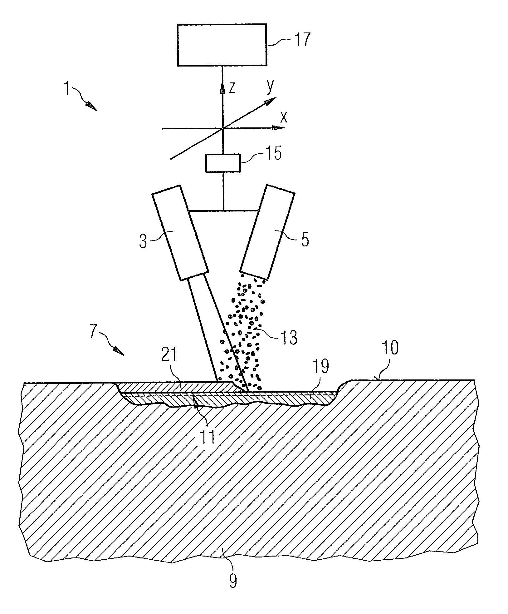
Method for welding workpieces made of highly heat-resistant superalloys, including a particular mass feed rate of the welding filler material
a superalloy and mass feed technology, applied in welding/cutting media/materials, machines/engines, metal-working apparatus, etc., can solve the problems of high temperature and strong mechanical loads, cracks may occur in moving blades over time, and spread further, and achieve high strength, good welding quality, and increase the distribution coefficient
- Summary
- Abstract
- Description
- Claims
- Application Information
AI Technical Summary
Benefits of technology
Problems solved by technology
Method used
Image

Examples
Embodiment Construction
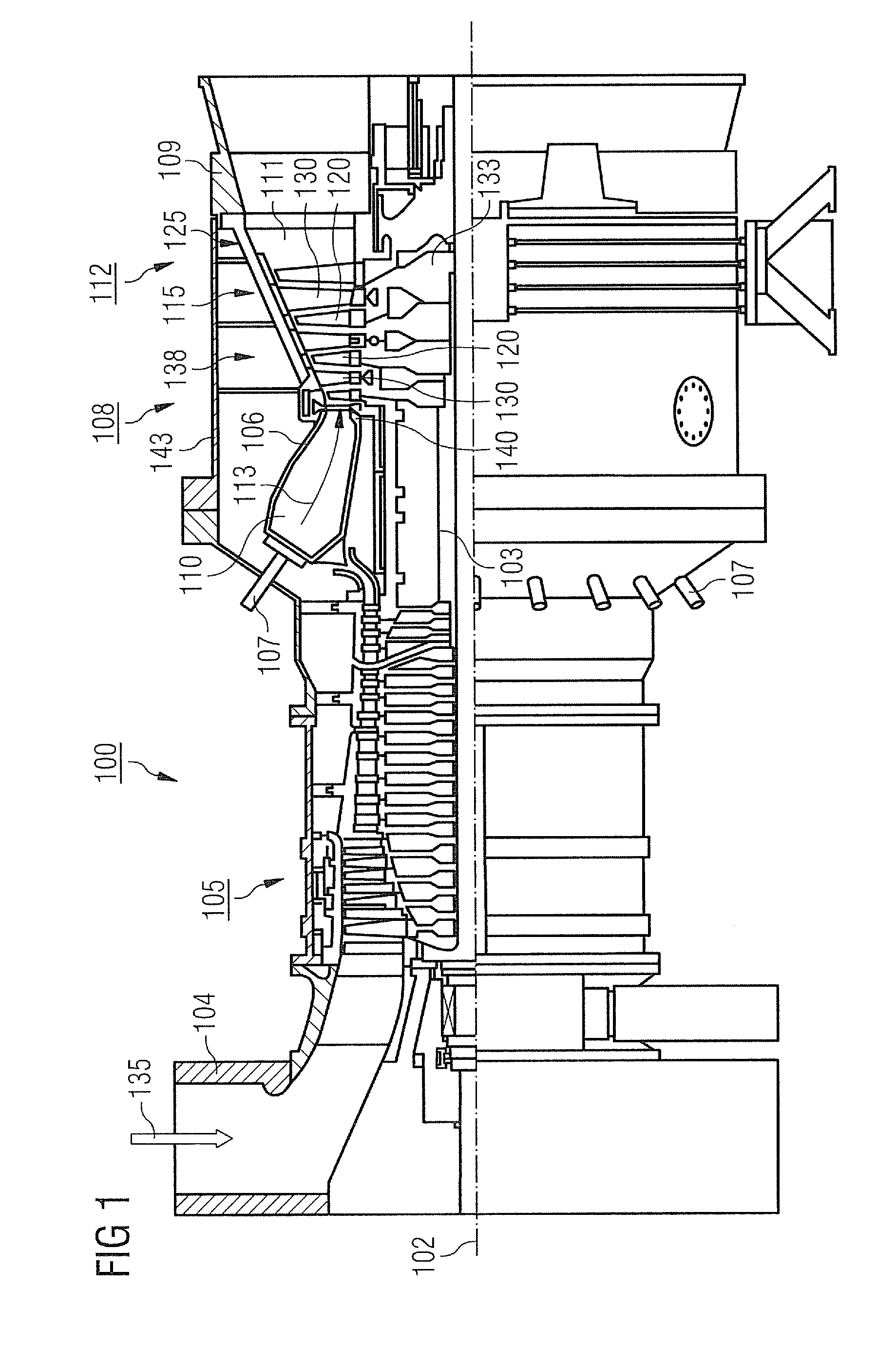
[0033]FIG. 1 shows by way of example a gas turbine 100 in a longitudinal partial section.
[0034]The gas turbine 100 has in the interior a rotor 103 with a shaft 101, which is rotatably mounted about an axis of rotation 102 and is also referred to as a turbine runner.
[0035]Following one another along the rotor 103 are an intake housing 104, a compressor 105, a combustion chamber 110, for example of a toroidal form, in particular an annular combustion chamber with a number of coaxially arranged burners 107, a turbine 108 and the exhaust housing 109.
[0036]The annular combustion chamber 110 communicates with a hot gas duct 111, for example of an annular form. There, the turbine 108 is formed for example by four successive turbine stages 112.
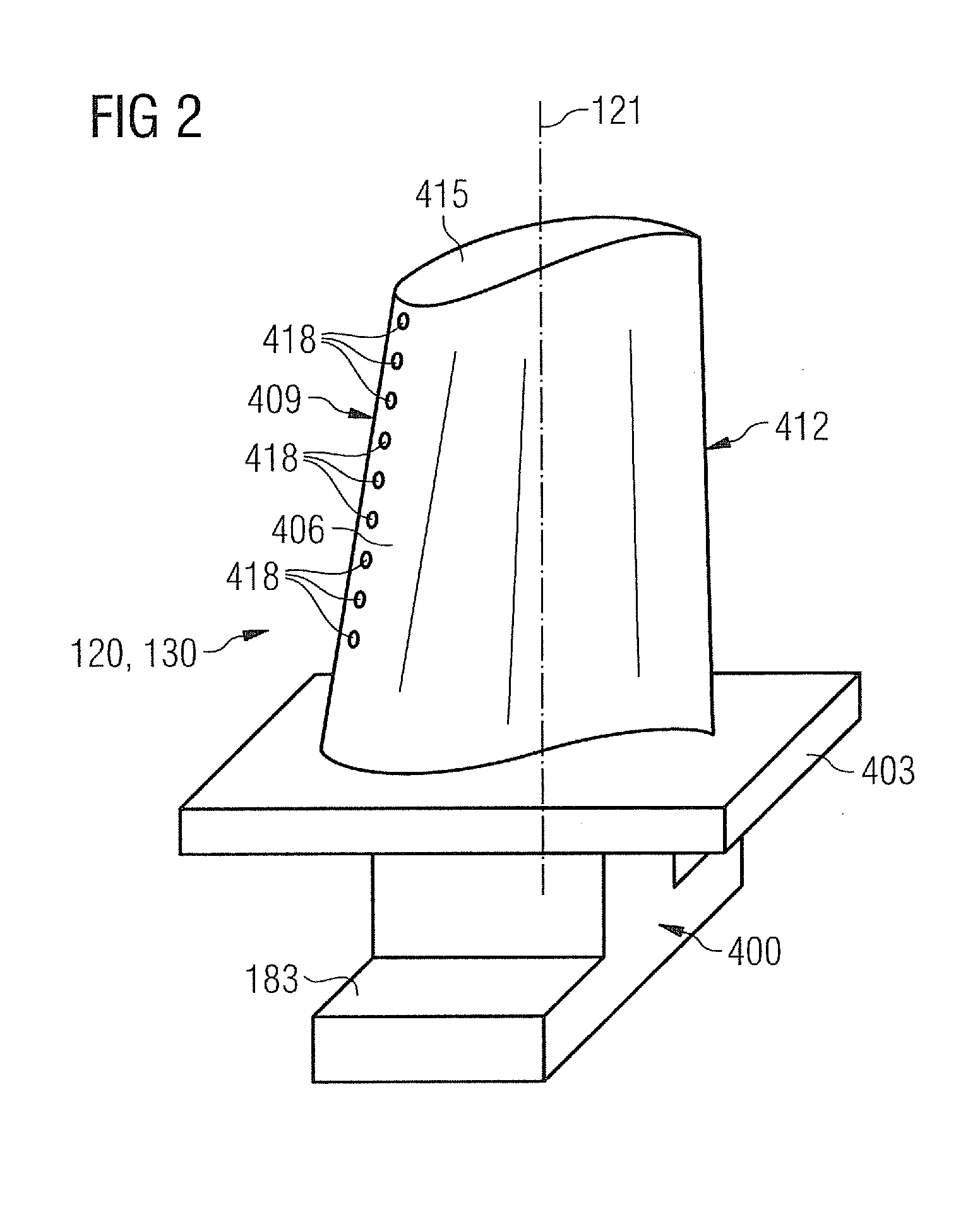
[0037]Each turbine stage 112 is formed for example by two blade rings. As seen in the direction of flow of a working medium 113, a row of stationary blades 115 is followed in the hot gas duct 111 by a row 125 formed by moving blades 120.
[0038]The stat...
PUM
| Property | Measurement | Unit |
|---|---|---|
| speed | aaaaa | aaaaa |
| speed | aaaaa | aaaaa |
| power | aaaaa | aaaaa |
Abstract
Description
Claims
Application Information