[0009]An object of the present invention to improve the quality of MR angiography images, particularly for patients with low
cardiac output.
[0010]According to a first aspect of the present invention, a method is provided to generate an MR angiography image of a vascular structure of an examination region in which spins in the examination region are saturated by
radiation of at least one RF saturation pulse, and in which these spins have a lower
signal intensity in the subsequent MR
signal acquisition for the generation of the MR angiography image, compared to spins that flow from a major artery via a feed artery into the examination region and are not saturated by the at least one RF saturation pulse, and that thus have a significantly increased
signal intensity relative to the saturation spins. According to this aspect of the invention, the saturation volume is established by
radiation of the at least one RF saturation pulse in order to be able to depict the vascular structure in the examination region. According to the present invention, the saturation volume is established such that the major artery and the tissue surrounding the major artery are not situated at the level of the branching of the feed artery in the saturation volume. The MR angiography image can then subsequently be generated with the use of the established saturation volume. A basis of the present invention is the recognition that the tissue around the major artery at the level of the branching of the feed artery does not necessarily have interfering signal portions if it is not saturated. Therefore, it is possible to except this region around the major artery from the saturation. This means that the proportion of the flowing spins that were not saturated by the saturation pulse can be placed closer to the actually interesting vascular structure. The signal proportions of the spins that flow unsaturated into the examination region can thereby be increased, which is reflected in an improved
signal intensity in the vessels of the vascular structure to be depicted. According to the invention, the
visibility of the vessel tree is thereby increased up to the
peripheral branchings, even given patients with low
cardiac output. It has been recognized that the segment of the vascular structure that is located at the level of the branching of the feed artery does not need to be contained in the saturation volume, since the surrounding tissue provides no significantly bright signal portion in the actual
signal acquisition for the generation of the MR angiography image, even without saturation.
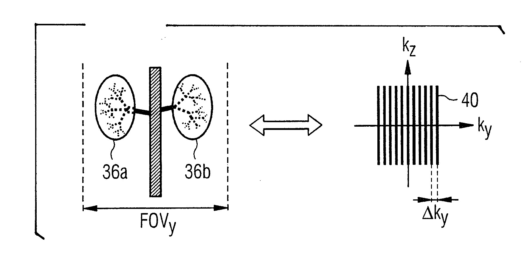
[0014]One possibility for application of the present invention is in the generation of MR angiography images of the two kidneys. It is hereby not necessary to include the
aorta at the level of the branching of the respective renal arteries in the saturation volume. The proportion of unsaturated spins in proximity to the renal arteries is thereby increased, such that overall the depiction of the vascular structure is improved since unsaturated blood can also penetrate into the smaller renal arteries until the switching of the next saturation pulse. Given the application of the invention for the generation of MR angiography images of the kidneys, two separate partial saturation volumes can now also be selected such that two oblique partial saturation volumes are selected that cover the kidneys themselves, but not the
aorta at the level of the branching of the respective renal arteries. Furthermore, the two partial saturation volumes can be selected such that the heart is included in neither of the two partial saturation volumes. A saturation of the spins within the heart should advantageously be avoided since otherwise the spins flowing into the
aorta would already be saturated before they flow into the saturation region.
[0016]For example, 2-dimensional or 3-dimensional, spatially selective inversion pulses can be used to saturate the spins within the saturation volume. With these spatially selective inversion pulses it is possible to invert the spins (and therefore saturate them) only in spatially delimited target volumes. The use of 2- or 3-dimensional, spatially selective inversion pulses can also be combined with parallel transmission techniques given the use of multiple transmission channels. Given the use of parallel transmission techniques with multiple channels, the selection of spatially delimited saturation volumes can be further improved.
[0017]Furthermore, it is possible to automatically identify the examination region via image post-
processing techniques, wherein the saturation volume is automatically determined depending on the identified examination region. For example, if the examination region is identified with the use of the image post-
processing technique as the region of the kidneys, the
system can be designed such that the information is stored that the aorta in the region of the branching of the renal arteries does not need to be saturated, such that the saturation volume can be automatically matched to this.
[0018]To calculate the two-dimensional or three-dimensional, spatially selective
inversion pulse, it is possible to base this on a calculation excitation
field of view or excitation k-space that is selected such that the corresponding dimension of the saturation volume in the examination subject covers only one or the two partial saturation volumes, and an edge of the saturation volume situated in the middle between the two partial saturation volumes. The saturation pulses thus can be designed to be of a shorter duration.

