
Vehicular insulation resistance detection apparatus

a detection apparatus and insulation resistance technology, applied in the direction of electric devices, instruments, transportation and packaging, etc., can solve the problems of erroneous detection of insulation resistance, instantaneous change of the capacitor, and malfunctions, so as to reduce the capacitance of the coupling capacitor, the effect of shortening the time from the occurrence of a ground faul

Active Publication Date: 2012-11-08
PANASONIC CORP
View PDF4 Cites 45 Cited by
  • Summary
  • Abstract
  • Description
  • Claims
  • Application Information

AI Technical Summary

Benefits of technology

[0013]An object of the present invention is to provide a vehicular insulation resistance detection apparatus that can shorten the time from occurrence of a ground fault until the insulation resistance becomes detectable without reducing the capacitance of coupling capacitors.

Problems solved by technology

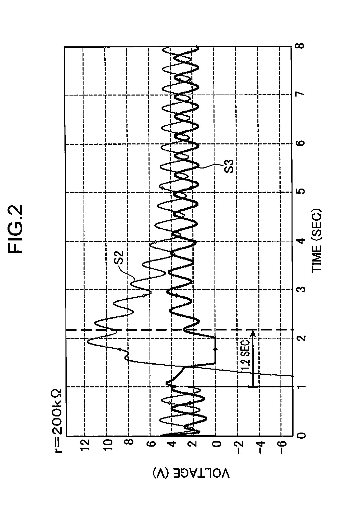
However, in the insulation resistance detection circuit described above, the moment a ground fault occurs, the voltage (potential) on the side of the insulation resistance detection circuit of the coupling capacitor undergoes an instantaneous change because of the high voltage of the high-voltage power source, whereby DC potential input to the A / D converter changes by several hundreds volts.
This means there is a time lag between a drop in insulation resistance caused by a ground fault or the like and issuance of an alarm to a passenger or a service man, which is not desirable.
However, the problem was that reducing the capacitance of the coupling capacitor would cause the voltage thereof more variable because of the influence of noise during driving of the vehicle or inverter noise and the like, which would lead to erroneous detection of insulation resistance and malfunctions.

Method used


Image

  • Vehicular insulation resistance detection apparatus
  • Vehicular insulation resistance detection apparatus
  • Vehicular insulation resistance detection apparatus

Examples


Embodiment Construction

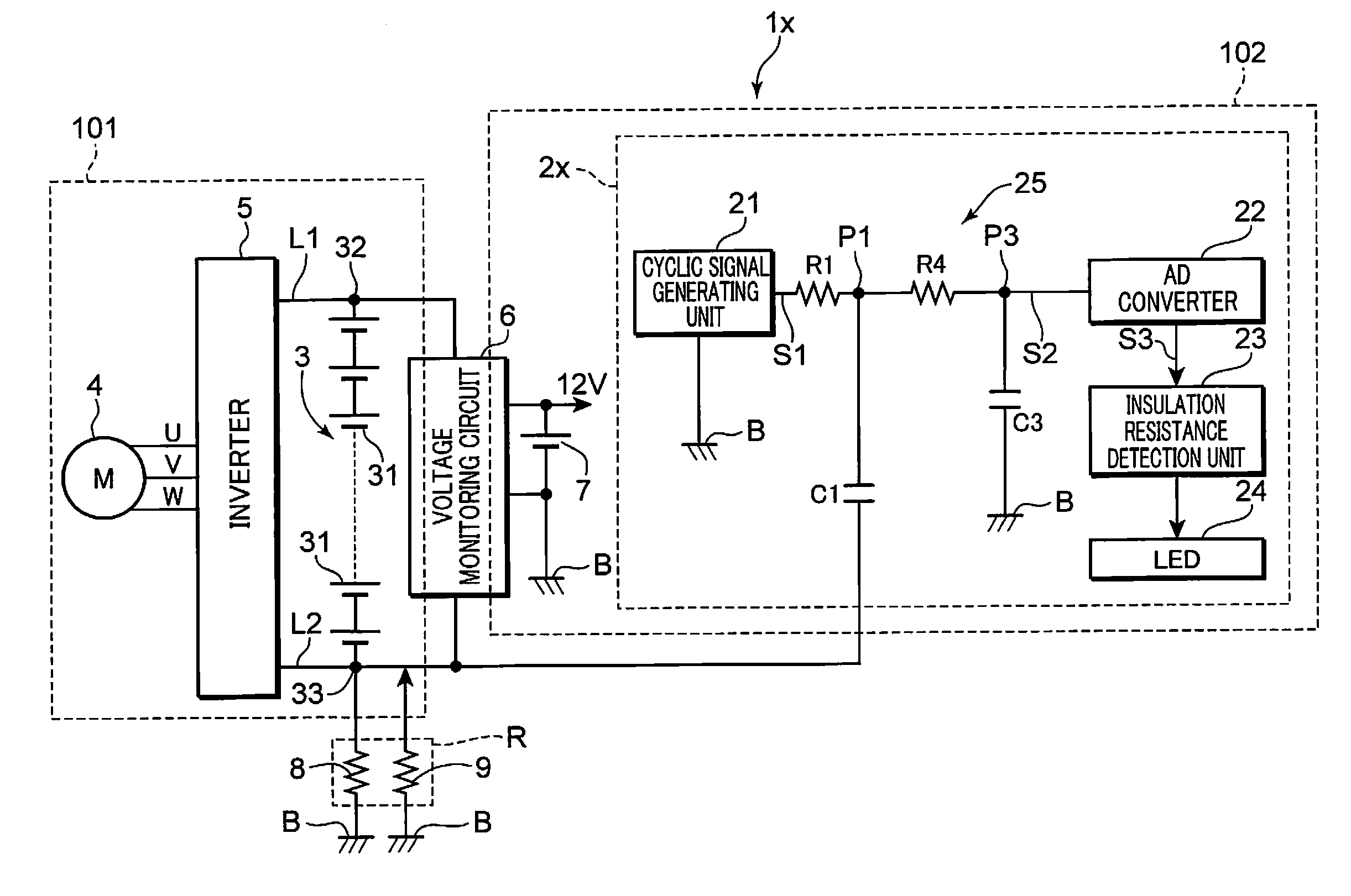
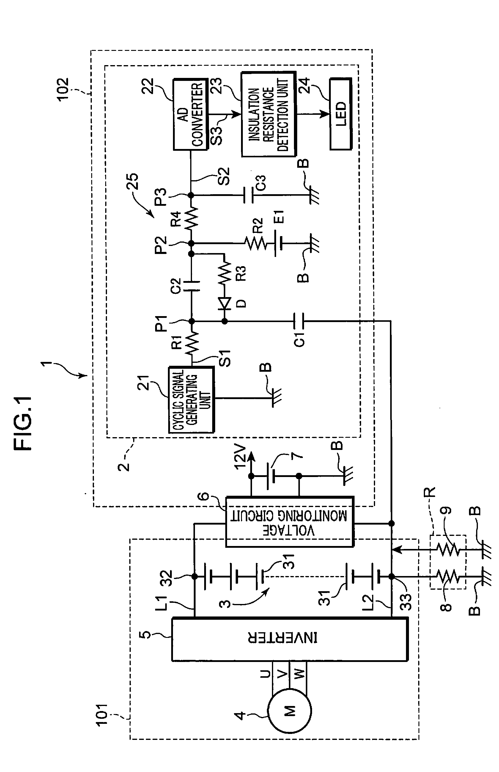
[0028]Hereinafter, embodiments of the present invention will be described based on the drawings. Same reference numerals given to components in various drawings indicate that these are the same components and description thereof will be omitted. FIG. 1 is a circuit diagram showing one example of the configuration of the vehicle equipped with the insulation resistance detection apparatus according to one embodiment of the present invention. The vehicle 1 shown in FIG. 1 is an electric car such as, for example, a hybrid car or a fuel cell car. Vehicles here include various vehicles other than hybrid cars and fuel cell cars, such as electric cars that do not use an internal combustion engine, electric bicycles, and the like.

[0029]The vehicle 1 shown in FIG. 1 includes a motor 4, a battery pack 3, an inverter 5, a voltage monitoring circuit 6, a rechargeable battery 7, and an insulation resistance detection apparatus 2. The insulation resistance detection apparatus 2 is one example of t...


PUM


Abstract

The vehicular insulation resistance detection apparatus includes a cyclic signal generating unit that generates a cyclic signal, a first resistor that has one end to which the cyclic signal is applied, a first capacitor that has one end connected to the other end of the first resistor and the other end connected to a high-voltage circuit, a second capacitor that has one end connected to the other end of the first resistor, a second resistor that has one end connected to the other end of the second capacitor and the other end connected to a low-voltage ground that is a circuit ground of a low-voltage circuit, a series circuit that includes a diode and a third resistor connected in series, and is connected in parallel with the second capacitor, this diode having a forward direction coincident with a direction from the other end of the second capacitor to the one end of the second capacitor, a voltage detection unit that detects a voltage between the low-voltage ground and the other end of the second capacitor as a detection signal, and an insulation resistance detection unit that detects a resistance value of an insulation resistance based on an amplitude of the detection signal.

Description

TECHNICAL FIELD[0001]The present invention relates to a vehicular insulation resistance detection apparatus for detecting insulation resistance between a low-voltage circuit and a high-voltage circuit.BACKGROUND ART[0002]Recent years have seen widespread use of hybrid cars that use an engine and an electric motor in combination, as well as increasing use of electric cars. Such vehicles that use an electric motor as a power source are equipped with a high-voltage power source that outputs a high voltage of, for example, about 288 V to 600 V as the power source for driving the motor. Such a high-voltage power source is formed by a battery pack of a plurality of series-connected rechargeable batteries such as, for example, lithium ion rechargeable batteries or nickel metal hydride rechargeable batteries.[0003]A high-voltage circuit, which is a circuit connected to the high-voltage power source, including the motor or an inverter to which power supply voltage is supplied from this high-...

Claims


Application Information

Patent Timeline
IPC IPC(8): G01R27/14
CPCB60L3/0069G01R31/025G01R27/18G01R27/025G01R31/52G01R27/08
Inventor MORIMOTO, NAOHISA
Owner PANASONIC CORP
Learn More