Modulator, filter, method of controlling gain of filter, and code modulating method

a modulator and filter technology, applied in the field of modulators, filters, methods of controlling the gain of filters, and code modulation methods, can solve the problems of increasing the cost of a modulator, affecting the efficiency of the modulator, so as to achieve low cost, low power consumption, and small size

Inactive Publication Date: 2012-11-08
LENOVO INNOVATIONS LTD HONG KONG
View PDF3 Cites 2 Cited by
  • Summary
  • Abstract
  • Description
  • Claims
  • Application Information

AI Technical Summary

Benefits of technology

[0051]According to the present invention, the modulator is provided which can be made small in size, low in costs, low in power consumption, small in heat generation and spurious signals. Also, the present invention provides the modulator which can easily improve signal quality by increasing computing accuracy. Moreover, the present invention provides the modulator which can decrease spurious signals.

Problems solved by technology

the multiplications among pluralities of bits occur the number of times being twice the product obtained by multiplying the number of taps of the FIR filter by a clock frequency (product of a chip-rate frequency and oversampling rate) per unit time, which causes an enormous amount of operations.
This presents problems in that a computing circuit becomes large in scale, causing difficulties in miniaturization and increased costs for a modulator.
Also, power consumption to operate the circuit is increased, which causes an increase in heat generation.
Another problems arise in that, when computing accuracy is to be made higher to improve signal quality, an amount of computation also increases, which makes the computing circuit further larger in scale and increases the consumption power, still further leading to difficulties in the improvement of signal quality.

Method used


Image

  • Modulator, filter, method of controlling gain of filter, and code modulating method
  • Modulator, filter, method of controlling gain of filter, and code modulating method
  • Modulator, filter, method of controlling gain of filter, and code modulating method

Examples


first embodiment

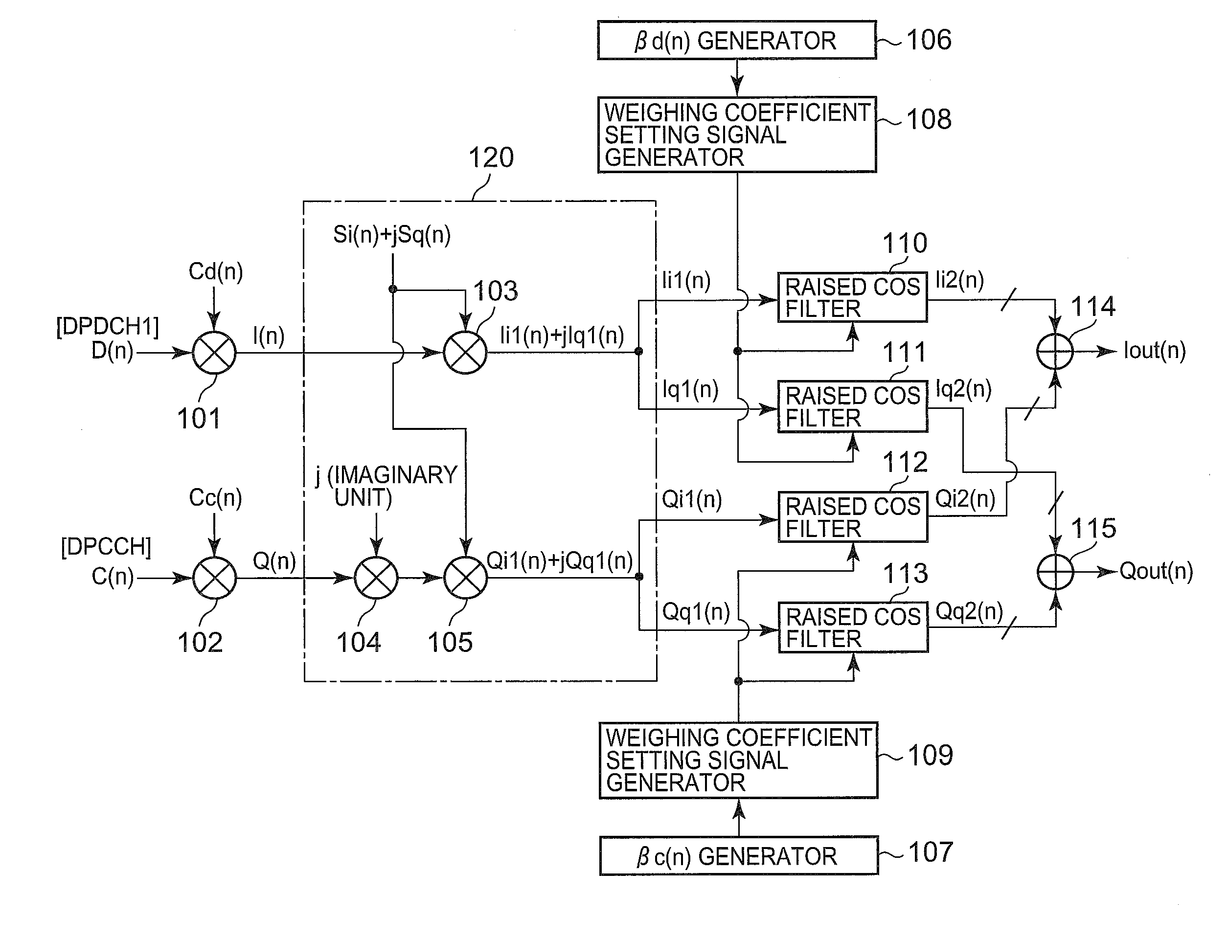
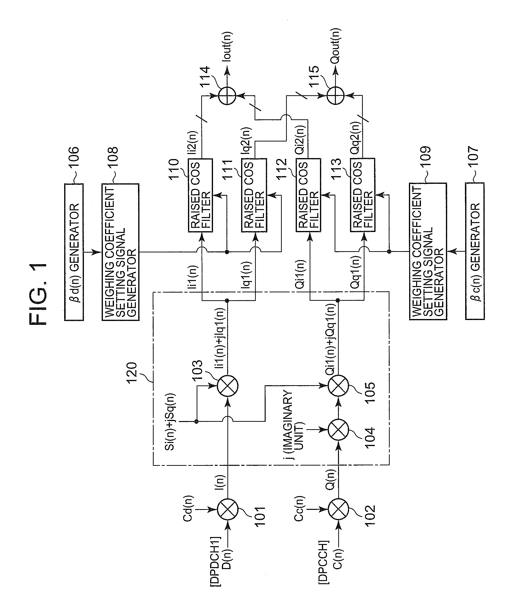
[0094]FIG. 1 is a diagram showing configurations of a modulator of the first embodiment of the present invention. The modulator of the first embodiment includes a code modulating section (made up of multipliers 101 and 102, complex-number computing section 120) to receive transmitted data to code-modulate the received data and to output the code-modulated data, a gain control signal generating section (made up of a data channel gain factor signal generator 106 and control channel gain factor signal generator 107) to generate a gain control signal, a filter section (made up of raised cosine filters 110 to 113) to receive an output from the code modulator and to restrict bandwidth and to output bandwidth-restricted signals, and a gain control section (made up of weighting coefficient setting signal generators 108 and 109) to receive an output form the gain control signal generating section and to control a gain of the filter section.

[0095]The modulator of the present invention is feat...

second embodiment

[0167]FIG. 3 is a block diagram showing configurations of a raised cosine filter of the second embodiment of the present invention. Basic configurations of the raised cosine filter of the second embodiment are the same as those in the first embodiment and differ from those in that a different method of setting a weighting coefficient of a FIR filter is employed.

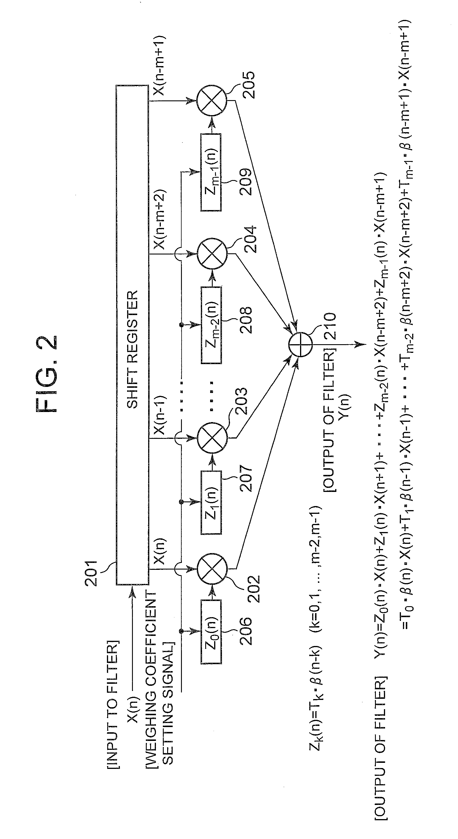
[0168]The raised cosine filter of the second embodiment includes a shift register section (shift register 301) to perform a shifting operation on an inputted signal X(n) and to output the signal as time-series data (X(n), X(n−1), . . . , X(n−m+2), X(n−m+1) each consisting of a plurality of signals containing past inputted signals, a shift register (shift register 302) to receive a gain control signal β(n) and to perform a shifting operation thereon and to output the signal as time-series data β(n−1), . . . , β(n−m+2), β(n−m+1) each consisting of a plurality of signals containing past gain control signals, a plurality of first...

third embodiment

[0187]FIG. 4 is a block diagram showing configurations of a raised cosine filter of the third embodiment of the present invention. Basic configurations of the raised cosine filter of the third embodiment are the same as those in the first embodiment and differ from those in that another different method of setting a weighting coefficient of the FIR filter is employed.

[0188]The raised cosine filter of the third embodiment includes a shift register section (shift register 401) to perform a shifting operation on an inputted signal X(n) and to output the signal as time-series data (X(n), X(n−1), . . . , X(n−m+2), X(n−m+1) each consisting of a plurality of signals containing past inputted signals, a plurality of register sections (shift registers 402, 403, 404, and 405) to receive and store the first and second weighting coefficients according to a gain control signal and to switch the first and second weighting coefficients for outputting according to a plurality of signals output from ...


PUM


Abstract

A modulator being made small in size, low in costs, low in power consumption, small in heat generation and spurious signals. The modulator includes multipliers (101, 102) for code-modulating received transmission data (D(n), C(n)), and outputting the modulated data, a control channel gain factor signal generator (106) for generating a gain control signal, a control channel gain factor signal generator (107), and weighting coefficient setting signal generators (108, 109) for receiving the output of the complex-number computing section (120) and controlling the gains of the raised cosine filters (110 to 113).

Description

REFERENCE TO RELATED APPLICATION[0001]This application is a continuation application of Ser. No. 12 / 088,566 filed on Mar. 28, 2008 and claims the benefit of the priority of Japanese patent application No. 2005-281893 filed on Sep. 28, 2005, the disclosure of which is incorporated herein in its entirety by reference thereto.TECHNICAL FIELD[0002]The present invention relates to a modulator, filter, method of controlling a gain of a filter, and a code modulating method and more particularly to the digital modulator for use in wireless communication or a like whose amplitude level can be set for every channel multiplexed through encoding and to the filter included in the modulator, the method of controlling a gain of a filter, and the code modulating method.BACKGROUND TECHNOLOGY[0003]In a communication system using a W-CDMA (Wideband Code Division Multiple Access) communication method, at the time of communication through an uplink from a mobile station to a base station, an HPSK (Hybri...

Claims


Application Information

Patent Timeline
Patent Type & Authority Applications(United States)
IPC IPC(8): H04B1/66H04B14/04H04B1/707
CPCH04L27/20H04L25/03834H04B1/7093
Inventor OGA, TOSHIYUKI
Owner LENOVO INNOVATIONS LTD HONG KONG
Why Eureka
Try Eureka