Method for heat-treating metal tubes or pipes for nuclear power plant, batch-type vacuum heat treatment furnace used therefor, and metal tubes or pipes for nuclear power plant heat-treated by the same
- Summary
- Abstract
- Description
- Claims
- Application Information
AI Technical Summary
Benefits of technology
Problems solved by technology
Method used
Image

Examples
example
[Example]
[0082]A test for obtaining a metal tube or pipe by subjecting it to precipitation heat treatment by using the method for heat treating a metal tube or pipe for a nuclear power plant of the present invention and the batch-type vacuum heat treatment furnace used therefor was performed to verify advantageous effects of the present invention.
[Test Method]
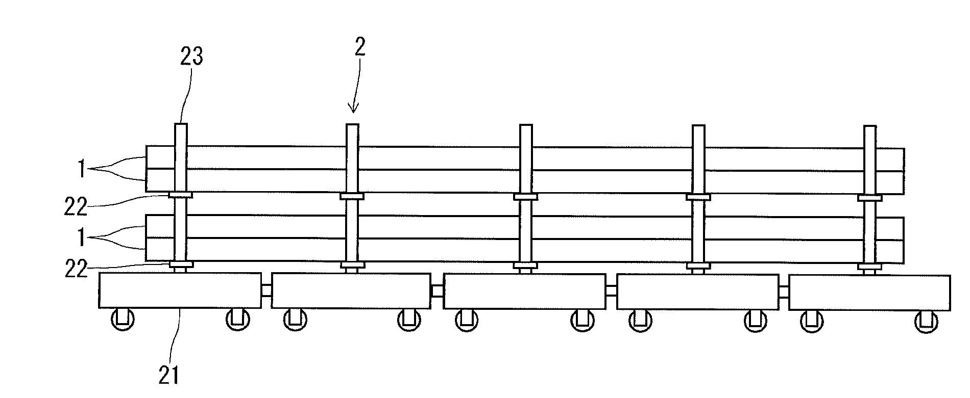
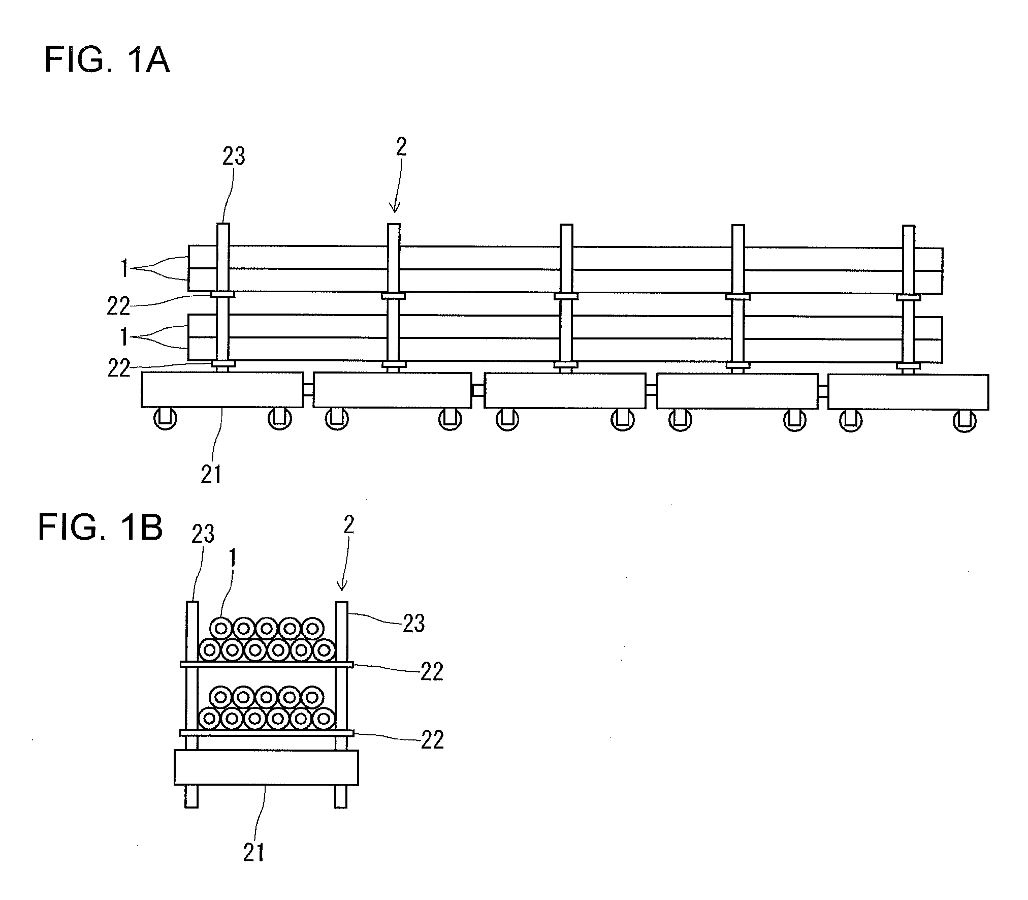
[0083]In the cart shown in FIGS. 1A and 1B described above, a heat resistant fabric was disposed on the surface of metal cross beams so that a metal tube or pipe and metal cross beams were set in indirect contact with each other by virtue of the heat resistant fabric interposed in between, and after the cart was accommodated in a batch-type vacuum heat treatment furnace, the interior of the furnace, which was evacuated in vacuum, was heated to perform heat treatment of the tube or pipe, thereby obtaining the intended metal tube or pipe. The conditions thereof were as follows.
[0084]Tube: outer diameter 19.05 mm, wall thickness 1...
PUM
| Property | Measurement | Unit |
|---|---|---|
| Fraction | aaaaa | aaaaa |
| Fraction | aaaaa | aaaaa |
| Fraction | aaaaa | aaaaa |
Abstract
Description
Claims
Application Information
 - R&D
- Intellectual Property
- Life Sciences
- Materials
- Tech Scout
- Unparalleled Data Quality
- Higher Quality Content
- 60% Fewer Hallucinations
Browse by: Latest US Patents, China's latest patents, Technical Efficacy Thesaurus, Application Domain, Technology Topic, Popular Technical Reports.
© 2025 PatSnap. All rights reserved.Legal|Privacy policy|Modern Slavery Act Transparency Statement|Sitemap|About US| Contact US: help@patsnap.com