Flexible elongated chain implant and method of supporting body tissue with same

a flexible chain and chain technology, applied in the field of implants, can solve the problems of prolonged disability, limited treatment options for compression fractures and related deformities, and inability to reposition fractured bone,

Active Publication Date: 2012-11-15
DEPUY SYNTHES PROD INC
View PDF12 Cites 36 Cited by
  • Summary
  • Abstract
  • Description
  • Claims
  • Application Information

AI Technical Summary

Benefits of technology

[0027]In yet another embodiment, the present invention provides a method for augmenting adjacent vertebrae, the method comprising the steps of: creating a void in an intervertebral disc by removing tissue from the disc; inserting into the void an apparatus comprising a chain comprising at least one non-flexible body; and at least one flexible portion comprising a joint, wherein the at least one non-flexible body is adjacent to the at least one flexible portion, such that the chain fills the void created in the intervertebral disc.

Problems solved by technology

Vertebral compression fractures, as illustrated in FIG. 1, represent a generally common spinal injury and may result in prolonged disability.
Until recently, doctors were limited in how they could treat such compression fractures and related deformities.
However, this procedure may not reposition the fractured bone and therefore may not address the problem of spinal deformity due to the fracture.
Moreover, this procedure requires high-pressure cement injection using low-viscosity cement, and may lead to cement leaks in 30-80% of procedures, according to recent studies.
In rare cases, however, polymethyrnethacrylate or other cement leaks into the spinal canal or the perivertebral venous system and causes pulmonary embolism, resulting in death of the patient.
Disadvantages of this procedure include the high cost, the repositioning of the endplates of the vertebral body may be lost after the removal of the balloon catheter, and the possible perforation of the vertebral endplates during the procedure.
Such a cement leak may occur through the low resistance veins of the vertebral body or through a crack in the bone which was not appreciated previously.
Other complications include additional adjacent level vertebral fractures, infection and cement embolization.
The cement may be forced into the low resistance venous system and travel to the lungs or brain resulting in a pulmonary embolism or stroke.
One drawback of this system, however, is that the mesh implant is not well integrated in the vertebral body.
This can lead to relative motion between the implant and vertebral body, and consequently to a postoperative loss of reposition.
This is primarily due to the limited applicability of xenografts, transplants from another species.
It is not always possible or even desirable to use an autograft.
Furthermore, the removal of material, oftentimes involving the use of healthy material from the pelvic area or ribs, has the tendency to result in additional patient discomfort during rehabilitation, particularly at the location of the material removal.
Grafts formed from synthetic material have also been developed, but the difficulty in mimicking the properties of bone limits the efficacy of these implants.
Additionally, the strain to failure of cancellous bone is about 5-7%, while cortical bone can only withstand 1-3% strain before failure.
It should also be noted that these mechanical characteristics may degrade as a result of numerous factors such as any chemical treatment applied to the bone material, and the manner of storage after removal but prior to implantation (i.e. drying of the bone).

Method used


Image

  • Flexible elongated chain implant and method of supporting body tissue with same
  • Flexible elongated chain implant and method of supporting body tissue with same
  • Flexible elongated chain implant and method of supporting body tissue with same

Examples


Embodiment Construction

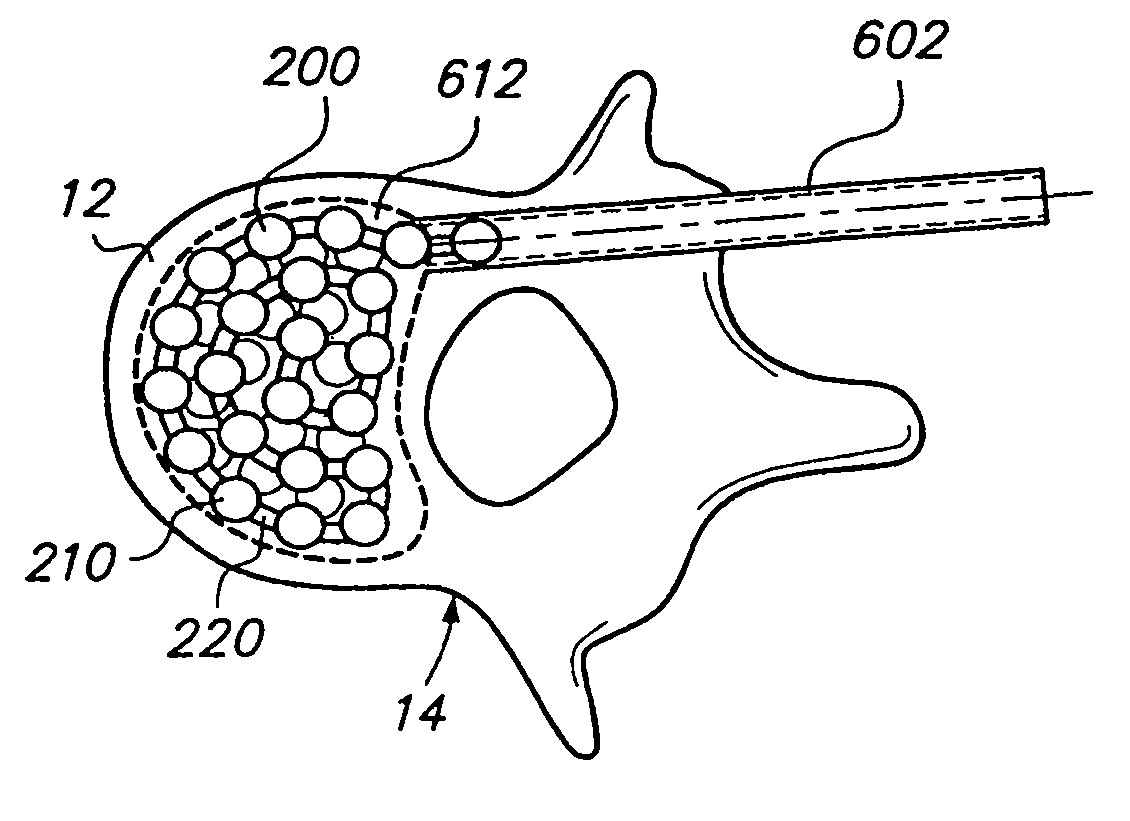
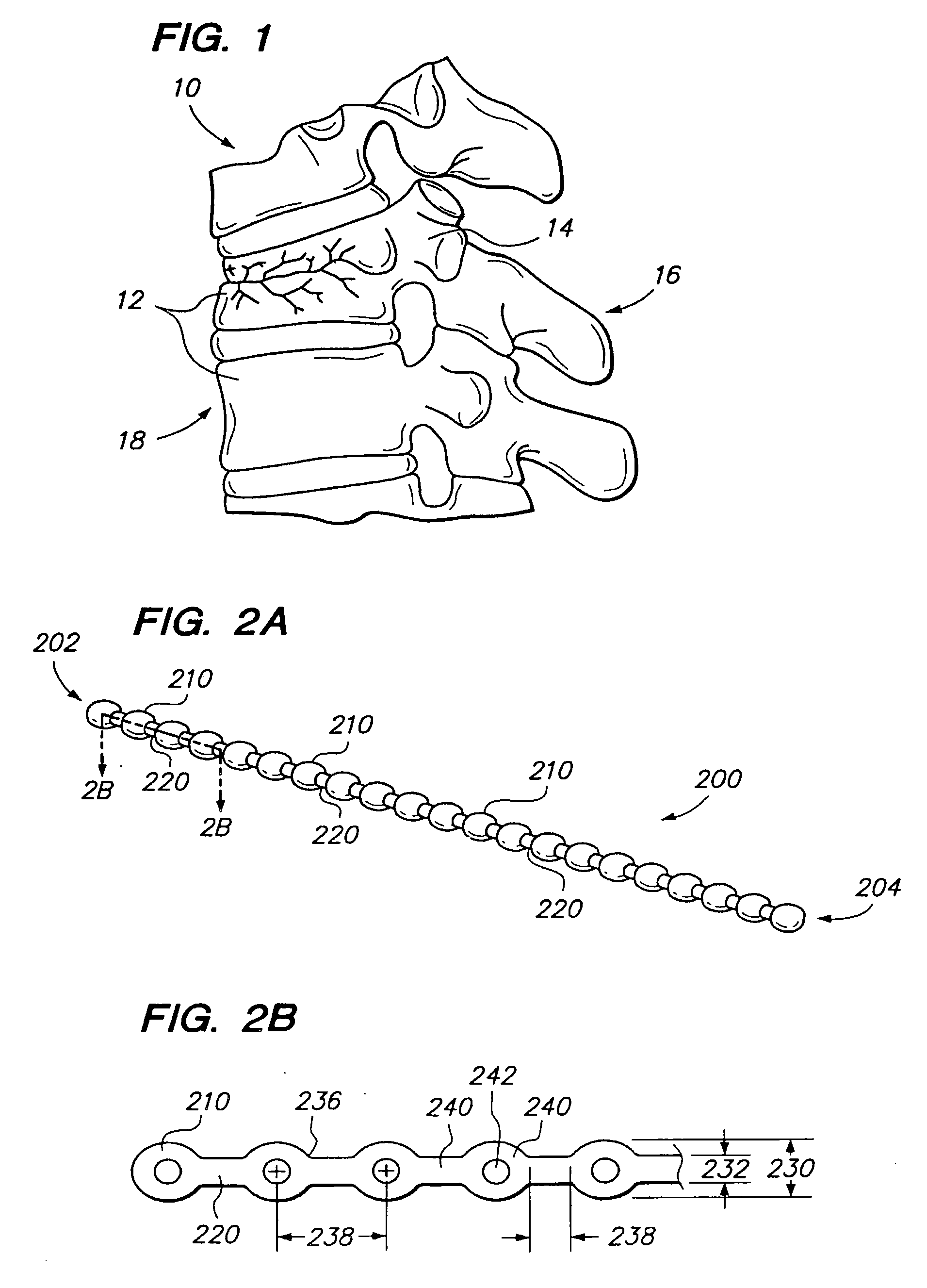
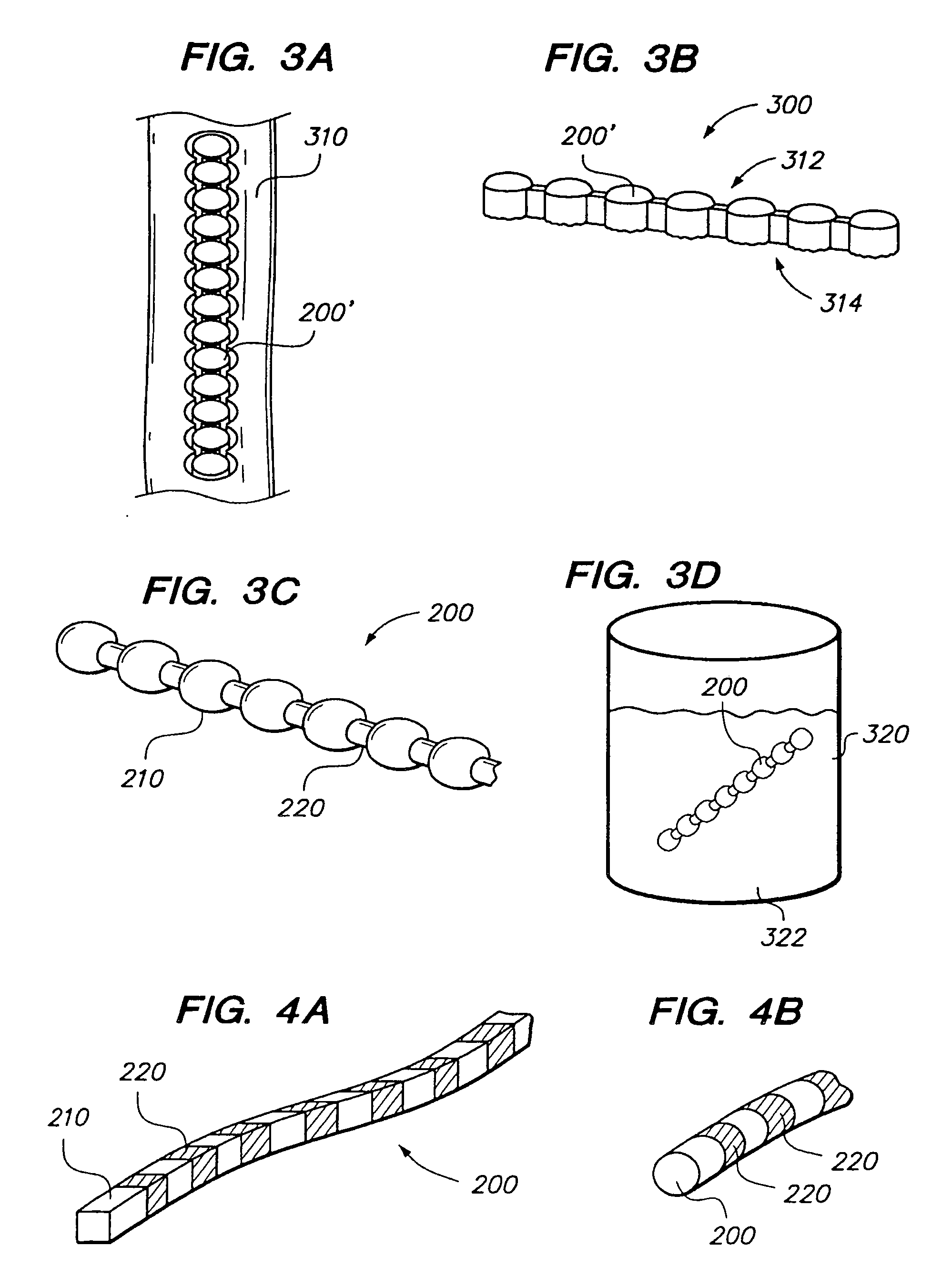
[0053]Referring to FIG. 2, a chain 200 (sometimes referred to as an elongated member) comprises one or more bodies 210 (sometimes referred to as beads). Chain 200 is preferably a monolithic chain, e.g., formed from a single, common material or type of material forming an integral structure. Bodies 210 are preferably substantially non-flexible, and may be solid, semi-solid, porous, non-porous, hollow, or any combination thereof. Chain 200 may also comprise one or more linking portions 220, also sometimes referred to as struts or links 220. Struts 220 may be disposed between each pair of adjacent bodies 210. Struts 220 are preferably substantially flexible or semiflexible, e.g. to allow for bending of the chain 200 between bodies 210.

[0054]Bodies 210 of chain 200 are preferably formed of bone, e.g., cortical bone, cancellous bone or both, but preferably cortical bone. In other embodiments, chain 200 may be comprised of any biocompatible material having desired characteristics, for exa...


PUM

PropertyMeasurementUnit
lengthaaaaaaaaaa
lengthsaaaaaaaaaa
compressive strengthaaaaaaaaaa

Abstract

Implants and methods for augmentation of the disc space between two vertebral bodies to treat disease or abnormal pathology conditions in spinal applications. The implant includes a chain of biocompatible material suitable for insertion into a disc space between two adjacent vertebral bodies in a patient's spinal column, wherein the spinal disc space has a transverse plane. The chain comprises a plurality of adjacent bodies having a height configured to reside within the disc space between two adjacent vertebral bodies and a length configured to reside in the disc space between two adjacent vertebral bodies when the chain is curved in an orientation substantially along the transverse plane of the spinal disc space.

Description

CROSS REFERENCE TO RELATED APPLICATIONS[0001]This application is a continuation application of U.S. patent application Ser. No. 11 / 633,131, filed Dec. 1, 2006, which claims priority under 35 U.S.C. §119(e) to U.S. Provisional Patent Application No. 60 / 753,782, filed Dec. 23, 2005 and U.S. Provisional Patent Application No. 60 / 810,453, filed Jun. 2, 2006, the entirety of each of which is incorporated by reference herein.FIELD OF INVENTION[0002]The invention relates to implants, and more particularly to flexible chain implants for augmenting or supporting bones or other structures, such as, for example vertebral discs.BACKGROUND OF THE INVENTION[0003]Vertebral compression fractures, as illustrated in FIG. 1, represent a generally common spinal injury and may result in prolonged disability. These fractures involve collapsing of one or more vertebral bodies 12 in the spine 10. Compression fractures of the spine usually occur in the lower vertebrae of the thoracic spine or the upper vert...

Claims


Application Information

Patent Timeline
Patent Type & Authority Applications(United States)
IPC IPC(8): A61F2/44
CPCA61B17/68A61B17/7094A61F2002/4415A61B2017/00526A61F2/44A61B2017/00004A61F2210/0004A61F2250/0003A61B17/88A61B17/70A61F2002/30593A61F2/3609A61F2/441A61F2/442A61F2/4455A61F2/4465A61F2/447
Inventor MESSERLI, DOMINIQUE
Owner DEPUY SYNTHES PROD INC
Why Eureka
Try Eureka