Imaging system and image processing apparatus

Inactive Publication Date: 2012-11-22
CANON KK
View PDF11 Cites 8 Cited by
  • Summary
  • Abstract
  • Description
  • Claims
  • Application Information

AI Technical Summary

Benefits of technology

[0013]The present invention in its second aspect provides an imaging system that acquires image data through imaging of an object, including: an imaging unit having an imaging optical system that forms an image of an object, and an imaging device that captures the image of the object formed by the imaging optical system; a stain method estimation unit that estimates a stain method of the object by analyzing image data of the object as obtained from the imaging unit; and a data reduction processing unit that reduces data volume of image data of the object if the stain method estimated by the stain method estimation unit is a predetermined stain method, wherein the data reduction processing unit includes a compression unit that compresses image data obtained from the imaging unit.
[0022]The present invention in its eleventh aspect provides a computer program stored on a non-transitory computer readable medium, the program causing a computer to perform a method including the steps of: acquiring image data of an object; estimating a stain method of the object by analyzing the acquired image data of the object; and reducing data volume of image data of the object if the estimated stain method is a predetermined stain method, wherein in the reduction step, a reduction method of data volume is decided in accordance with a file format of the image data.

Problems solved by technology

The method of Japanese Patent Application Publication No. 2010-216919 can potentially shorten processing time in cases where the proportion of objects to be imaged at high resolution is small.
Therefore, no gains in throughput can be achieved using the method disclosed in Japanese Patent Application Publication No. 2010-216919.
Conventional systems, however, were only capable of performing processing under identical conditions, regardless of the type of object, also in cases where objects for histological diagnosis and objects for cytological diagnosis were mixed.
Depending on the object, therefore, generation and recording of image data beyond required specifications (for instance, resolution, image quality, compression rate and so forth) results in lowered processing efficiency on account of the increased data volume.
This problem becomes particularly serious as the resolution and size of the images increase.
However, information required for observation and diagnosis may be lost when, in order to reduce data volume, resolution and / or image quality are lowered, and the compression rate is increased, across-the-board for all objects.

Method used


Image

  • Imaging system and image processing apparatus
  • Imaging system and image processing apparatus
  • Imaging system and image processing apparatus

Examples


first embodiment

Overall System Configuration

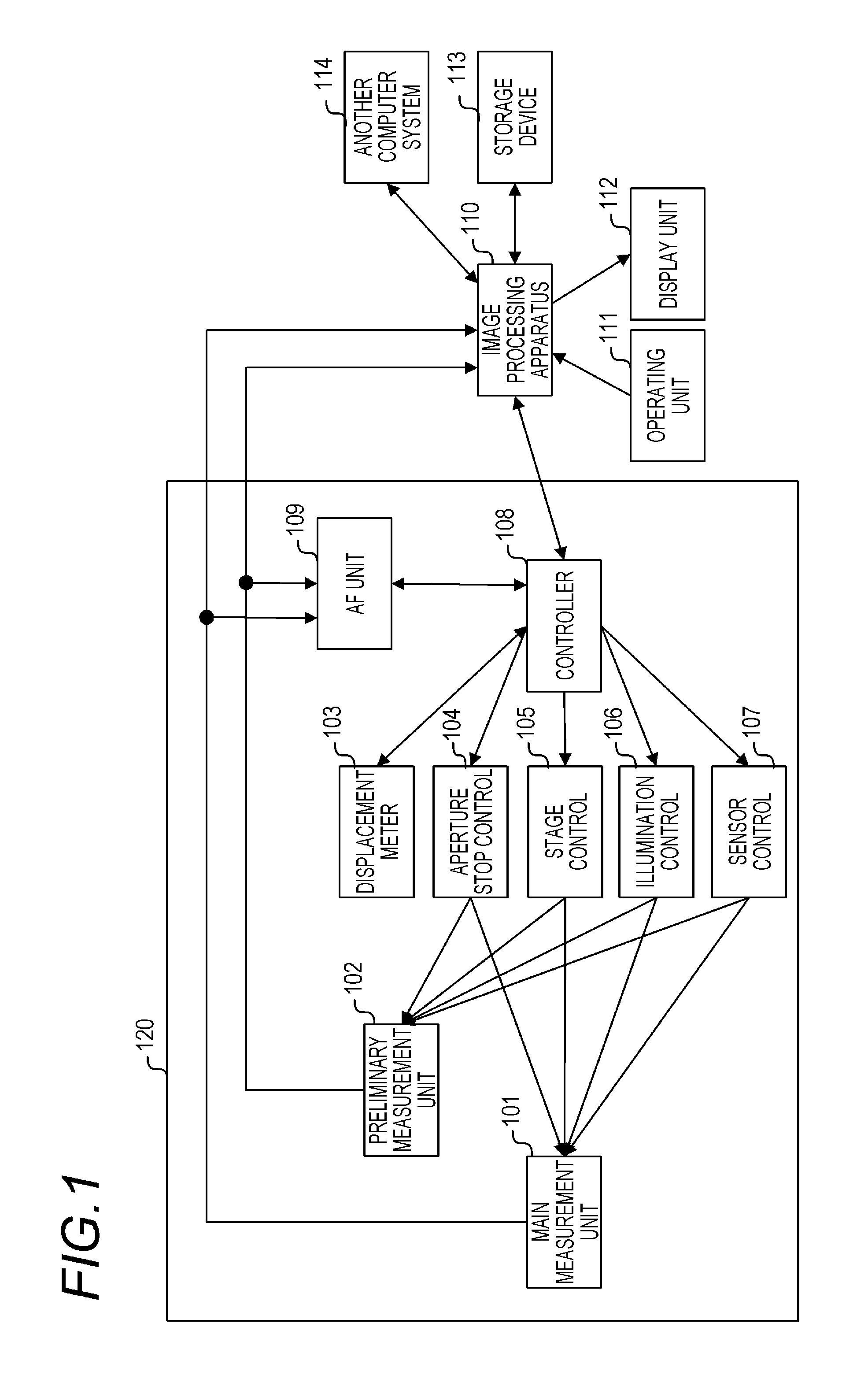
[0041]FIG. 1 illustrates a virtual slide system in an embodiment of an imaging system of the present invention.

[0042]The virtual slide system is made up of an imaging device (also referred to as virtual slide scanner) 120 that acquires image data of an object, an image processing apparatus (also referred to as host computer) 110 that performs data processing and control on the image data, and peripheral devices of the image processing apparatus 110.

[0043]The image processing apparatus 110 is connected to an operating unit 111 that receives inputs from a user via an operating device such as a keyboard or a mouse, and a display unit 112 that displays a processed image. A storage device 113 and another computer system 114 are connected to the image processing apparatus 110.

[0044]In a case where multiple objects (slides) are imaged, the imaging device 120 captures images of the each object sequentially, under the control of the image processing apparatus 110,...

second embodiment

[0135]In the second embodiment an example will be explained in which data volume is reduced through a binning process that utilizes a CMOS image sensor. The CMOS image sensor in the present embodiment is of APS (active pixel sensor) type, explained below, that is capable of reading a voltage signal amplified for each pixel.

[0136]In the CCD image sensor, charge moves according to a bucket brigade scheme, and is finally amplified collectively. As a result, charges can be aggregated during charge motion. In the case of a CMOS image sensor, however, the charge accumulated in each pixel is read through conversion to voltage and amplification, for each pixel. Accordingly, binning cannot be carried out during charge motion. In the present embodiment, therefore, an operation circuit for performing resolution conversion processing (pixel aggregation processing) is provided after the CMOS image sensor, so that a binning process is realized by performing a data operation on the output signal o...

third embodiment

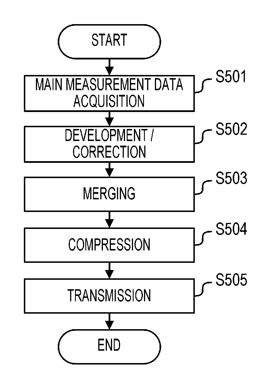
[0145]In the third embodiment an example will be explained wherein, unlike in the first and the second embodiment, data volume is reduced through modification of an image compression parameter in the compression processing S504 in the internal flow of the main measurement processing illustrated in FIG. 4A.

[0146]In the present embodiment, a JPEG compression / coding scheme will be explained as an example of an image compression scheme that is used in the compression processing S504. The present embodiment can be used in other compression / coding schemes such as JPEG2000, JPEG-XR and the like, since these are structured similarly to JPEG as regards image conversion processing and quantization processing. (For instance, JPEG2000 utilizes a wavelet transform instead of a discrete cosine transform).

[0147]A brief overview of the JPEG compression scheme will be explained first,

[0148]FIG. 13 illustrates a block diagram of a coding and a decoding device of a JPEG compression / coding scheme. The ...


PUM


Abstract

An imaging system that acquires image data through imaging of an object, includes: an imaging unit having an imaging optical system that forms an image of an object, and an imaging device that captures the image of the object formed by the imaging optical system; a stain method estimation unit that estimates a stain method of the object by analyzing image data of the object as obtained from the imaging unit; and a data reduction processing unit that reduces data volume of image data of the object if the stain method estimated by the stain method estimation unit is a predetermined stain method.

Description

BACKGROUND OF THE INVENTION[0001]1. Field of the Invention[0002]The present invention relates to an imaging system that acquires image data through imaging of multiple objects, and to an image processing apparatus that processes image data of multiple objects.[0003]2. Description of the Related Art[0004]Virtual slide systems, which enable pathological diagnosis on a display through imaging of test samples that are mounted on slides and through digitization of obtained images, have attracted attention in recent years, in the field of pathology, as substitutes of optical microscopes, which are one of the tools of pathological diagnosis. Digitization of pathological diagnosis images through the use of virtual slide system makes it possible to handle, in the form of digital data, images of test samples from conventional optical microscopy. This affords potential advantages in terms of, for instance, faster remote diagnosis, briefing to patients using digital images, sharing of rare case...

Claims


Application Information

Patent Timeline
IPC IPC(8): H04N7/18
CPCG02B21/365G02B21/34
Inventor MURAKAMI, TOMOCHIKA
Owner CANON KK
Why Eureka
Try Eureka